The Planetary Business Card project has convinced me it is time to make a slotting attachment for the mill. It will be used for making the gears for this project. It will also be useful for marking dials and other similar items. There is a good description of making a slotting attachment for a large lathe in Machinist's Workshop Aug/Sep 2010, pg 5 & Oct/Nov, pg 34. Its lever mechanism will ba adapted for this slotter.
The first order of business is deciding how to attach the device. The most flexibility comes from attaching it to the z-axis. The rotary table, indexing head, and x- & y-axes can then all be used as needed. My first plan was to mount it to the side of the spindle head where the motor is mounted. This presents a potential problem of torque as pressure is applied to the slotting lever and pushing the mill column out vertical. The second idea was the winner. The attachment can just replace the spindle altogether. This greatly simplifies the design. One block of material will serve to anchor the device and support the leveraging mechanism without running screw holes through the shaft hole.
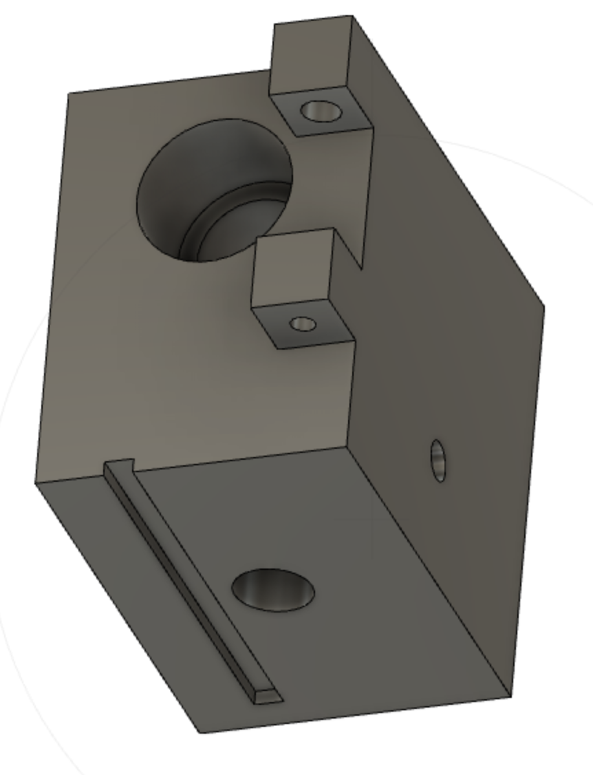
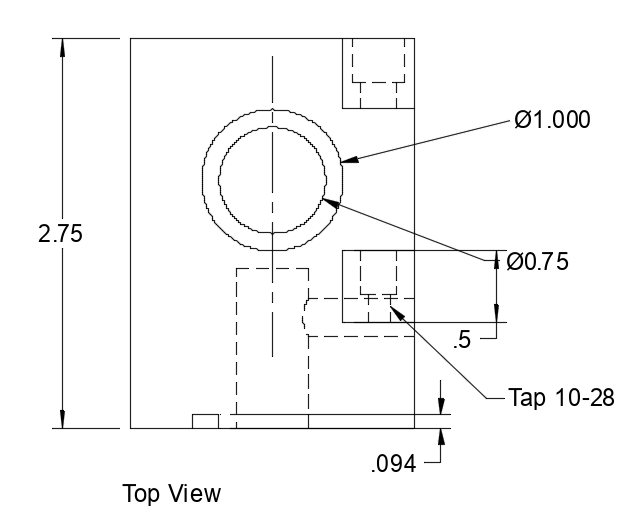
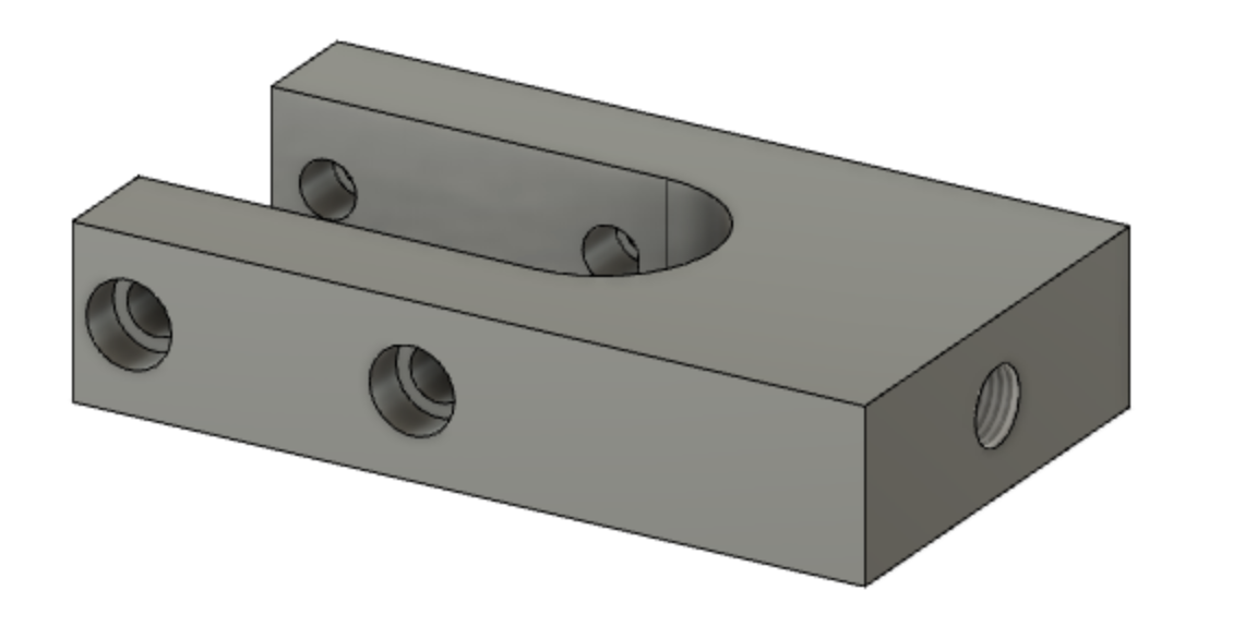
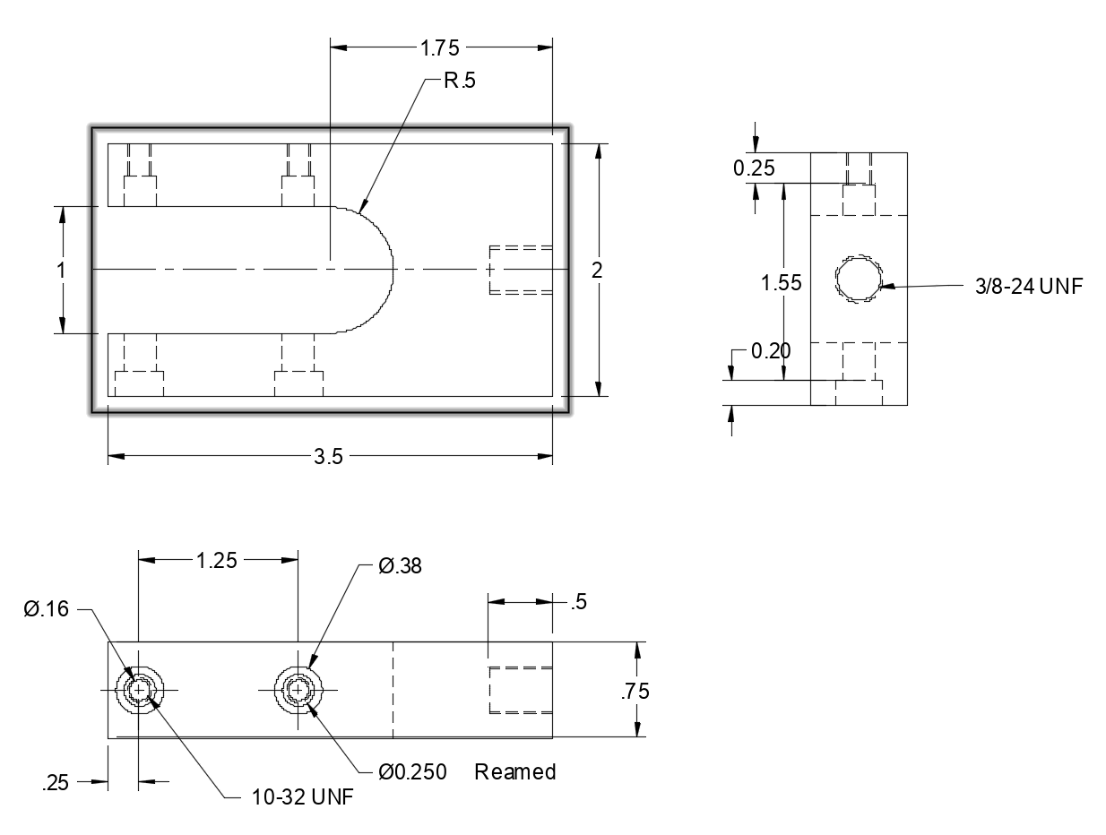
The block of material required for this main part of the slotter should be about 2 1/8" X 2 3/4" X 3". This is the approximate size of the current spindle housing. A hole is needed for the ram and its bearings sitting toward the front of the device. A large hole as well as a keyway are in the back. One side has a threaded hole for a set screw. Dimensions were taken and the main block was constructed in Fusion 360. The two pictures below show the results of this CAD work.
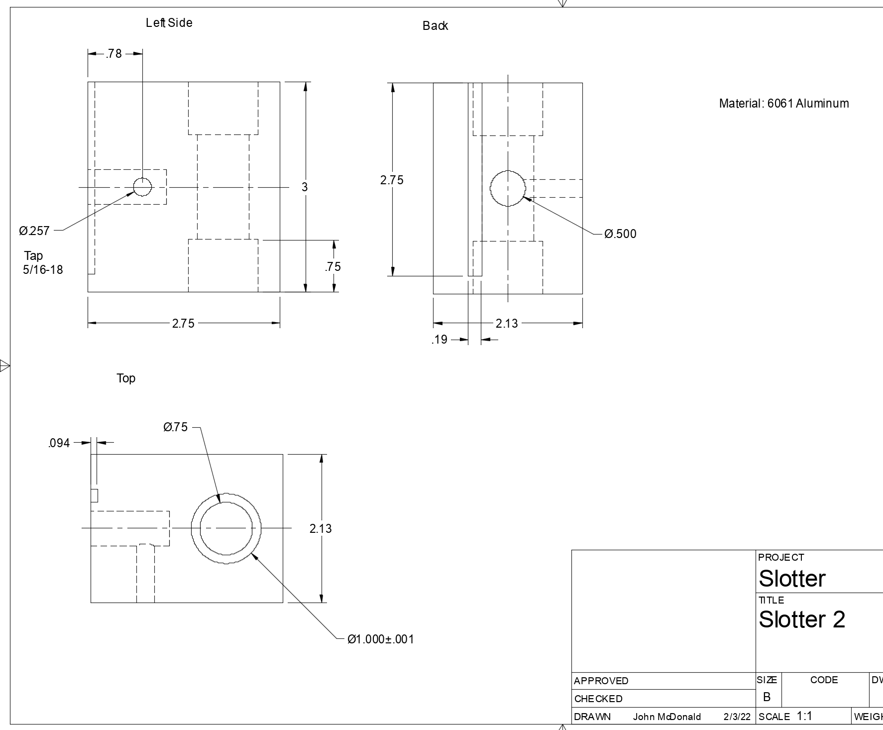
The only aspect of the drawing that is a little off is the hole for the ram. Two bronze or brass bearings will be inserted in the ends of this hole. They will be bored 0.750". The hole between these two bearing seats should be larger than 0.750" so the ram is supported only by the bearings. One additional feature may be added: a second set screw into the center of the ram hole from the front of the block. With a slot cut in the ram, this set screw could be used as a stop to cut precisely measured lines as on a dial.
Ordered the needed ingredients from Speedy Metals this afternoon. In addition to bronze for bushings, nylon 6/6 was also ordered. It will be tried as bushings to determine if it is as good or better than bronze for this sliding action.The aluminum block was ordered quite oversized (a 3" length of 2 1/2" X 3") as that is what was available. My current design is for a block 2 1/8" wide. I also need to add tabs to the top to support the lever mechanism. I called Speedy Metals to modify my order. I should finish the design work before ordering! Back to Fusion to add the tabs.
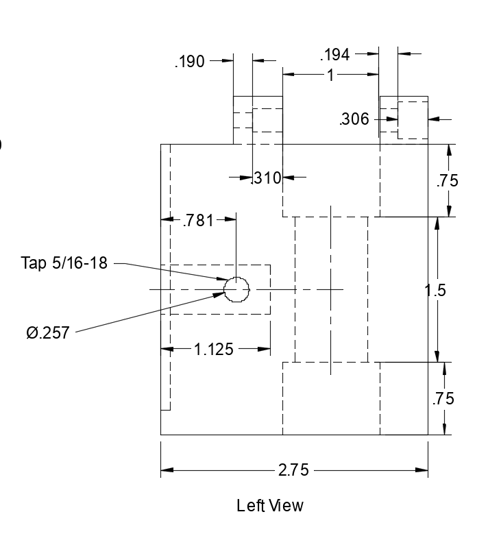
The new and improved plans are shown below. The Fusion 360 work is proceeding much more smoothly now. Repeating this exercise three times has been beneficial.
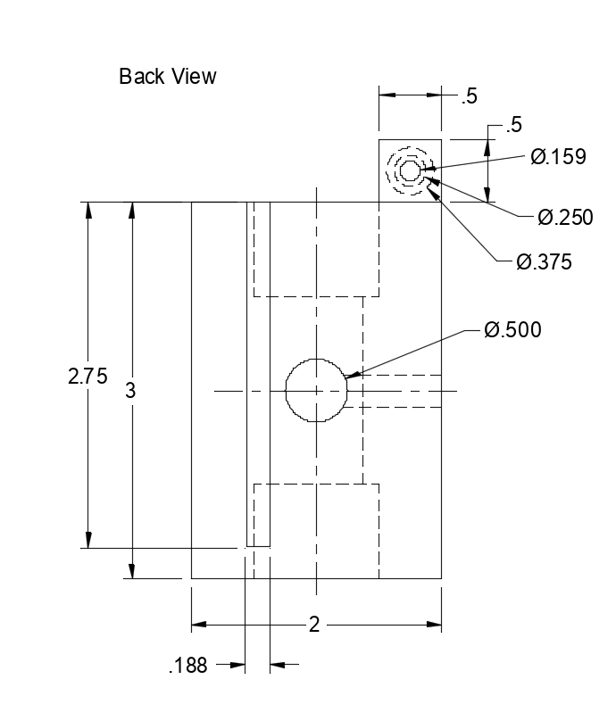
I would like for this to also be useful on the South Bend lathe. Consideration was given to adding flanges on the back to it could be clamped to the crosslide table on a support raising it to lathe center height. An easier alternative is mounting it in the vertical milling attachment. Center height can easily be adjusted as needed. I am considering putting multiple flats for the set screw that holds the cutting head in place. This will allow easy adjustment of the cutting orientation whether attached to the mill or in the lathe milling attachment.
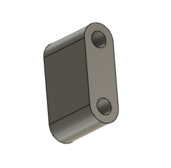
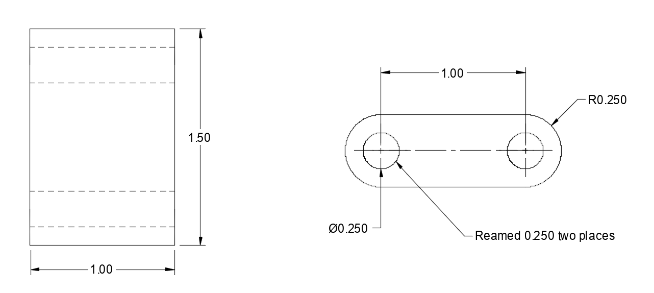
The simple 0.5" X 1.0" X 1.5" pivot link was created in Fusion next. The 3D render and the plan are shown below.
The yoke is a little more complex. The depth of the cutout may need to be modified as this is dependent on the distance between the ram and the tabs on the main body. These are not the same in my model as in the article. The yoke attaches to the handle. The handle in the article is made from 3/4" steel round. The handle here is made from 1/2" steel round. Consequently the screw hole in the yoke is threaded 3/8-24.
The handle and ball were drawn next as shown in the four screen captures below.
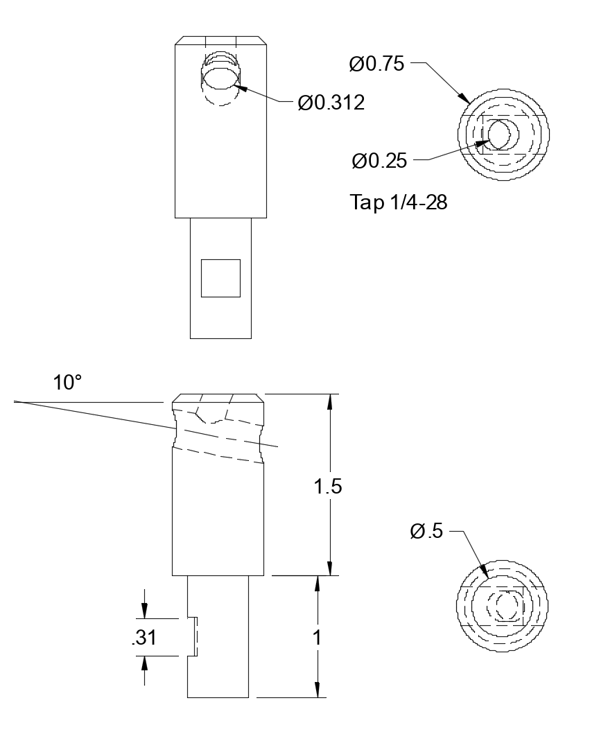
The ram and the tool holder. For the angled hole in the toolholder a sketch with a circle was created on the face of the cylinder. Then a line was drawn from the center of the circle to the opposite face at 10°. Sweep was used instead of extrude by selecting the circle and then the path (line).
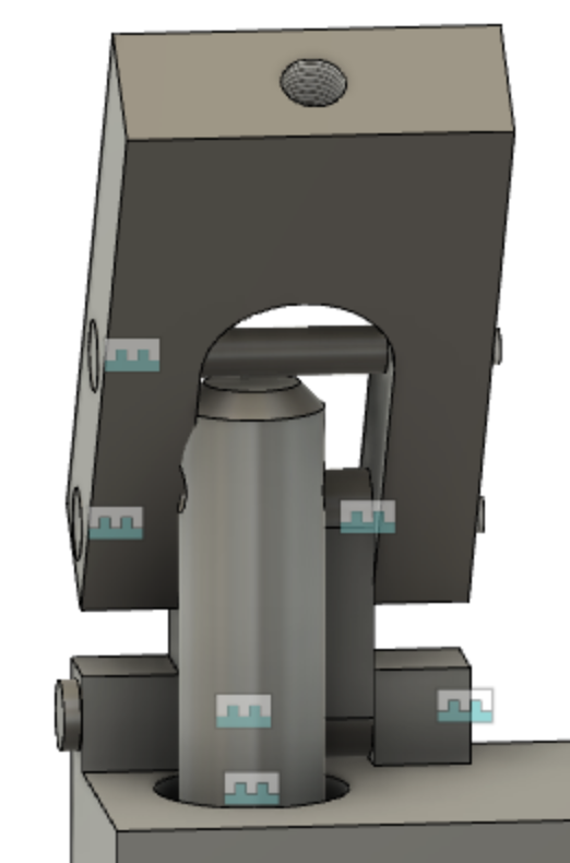
And finally the shoulder screws that are yet to be purchased, but needed to put the model together. These were quickly drawn. No plan is shown as they are not being made. I started working through the assembly. It is difficult as multiple things need to be selected to get the joint to work. For instance an axis on a bolt along with the face of the head need to be selected along with the hole and the appropriate buried face where the head seats. Just aligning the picture so I can see the things that need to be selected is challenging. The body and bolt were assembled first. This was followed by adding the pivot. The yoke and the bolt for the pivot were assembled and this was further joined to the other end of the pivot. The ram was joined to the body and a problem was discovered.
I saw a video on assembly. The most noteworthy part of the video is selecting things that are behind others. A modifier key held down during the selection process pops up a list of selectable items behind the pointer.
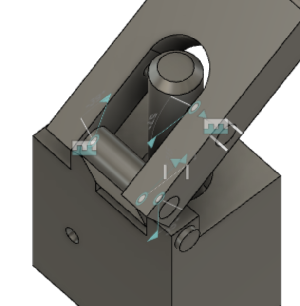
The ram does not align with the yoke as can be seen in the following screenshot. Of course, this is exactly why I wanted to learn how to use Fusion 360. I prefer to spot these errors before I cut metal. The hole for the ram needs to be moved to center it between the two tabs. That runs the risk of the ram hole running into the mounting hole. Lucky, lucky! The ram hole needs to be moved 3/16" and the distance between the support hole and the shaft is 0.44". There is 1/4" to spare. That assumes the hole drilled for the support is finished flat bottomed with an end mill.
The model was repaired in two places by going back to the original sketches and editing them. The ram hole shifted, but the drawings did not reflect this change. After many machinations I found a small chain icon in the application bar that drove the update. The drawings above now reflect the modification. The joints are in place as shown above, but I have not been able to get the last joint to form without yanking the shoulder bolt out of the yoke. I have posted a query asking how to do this on the Fusion 360 forum. After a little back and forth someone modified the model I posted and returned it. The animation shows good clearance between the top of the ram and the yoke!
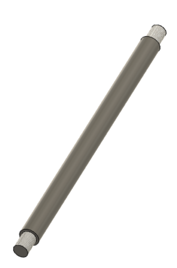
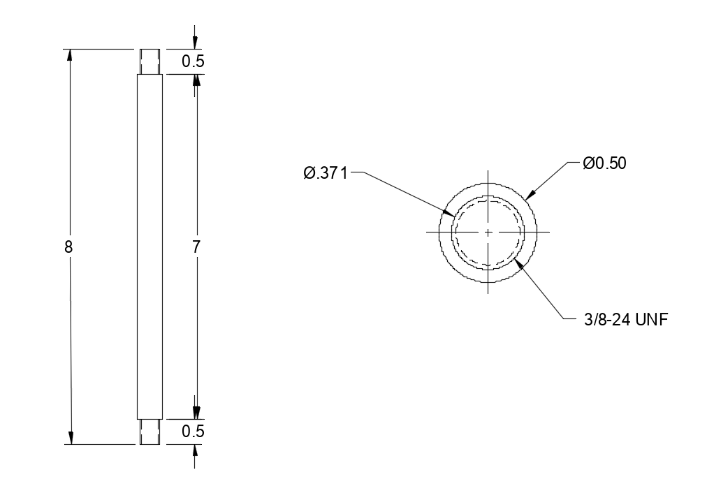
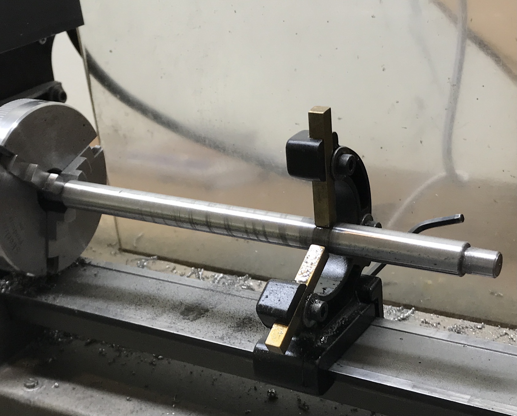
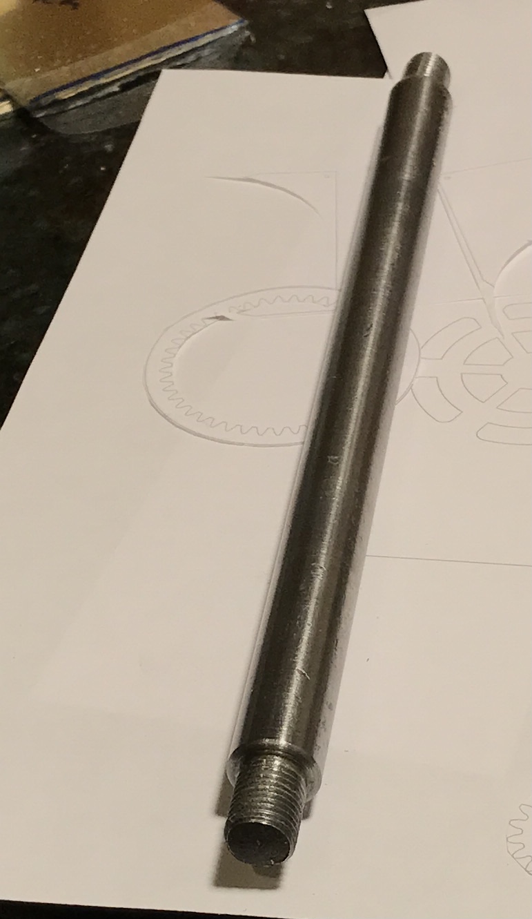
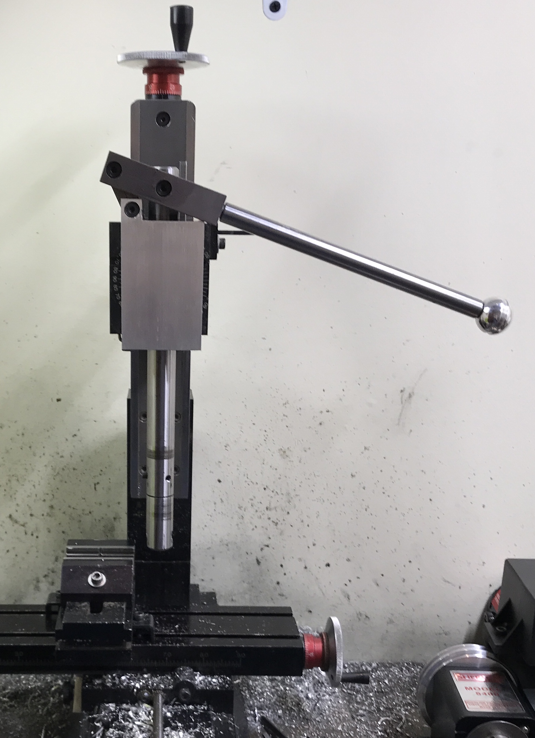
Made the first part in the lathe this morning, the handle. Found some crummy CRS and cut off an 8" length. It was held in the vise and a steady rest was positioned about 2" from the distal end. The free end was faced and 1/2" was reduced to 0.373". There was tremendous chatter. The steady rest did not hold the part no matter how tight its screws were turned. Thread relief was cut and all corners were chamfered. This was repeated on the opposite end. The shaft was sanded to a decent finish, though there are a lot of tiny divots and a line that runs the length. The first photo shows the lathe setup and the second the rod after threading ends 3/8-24. The threads on one end did not go on straight. That will be the handle end!
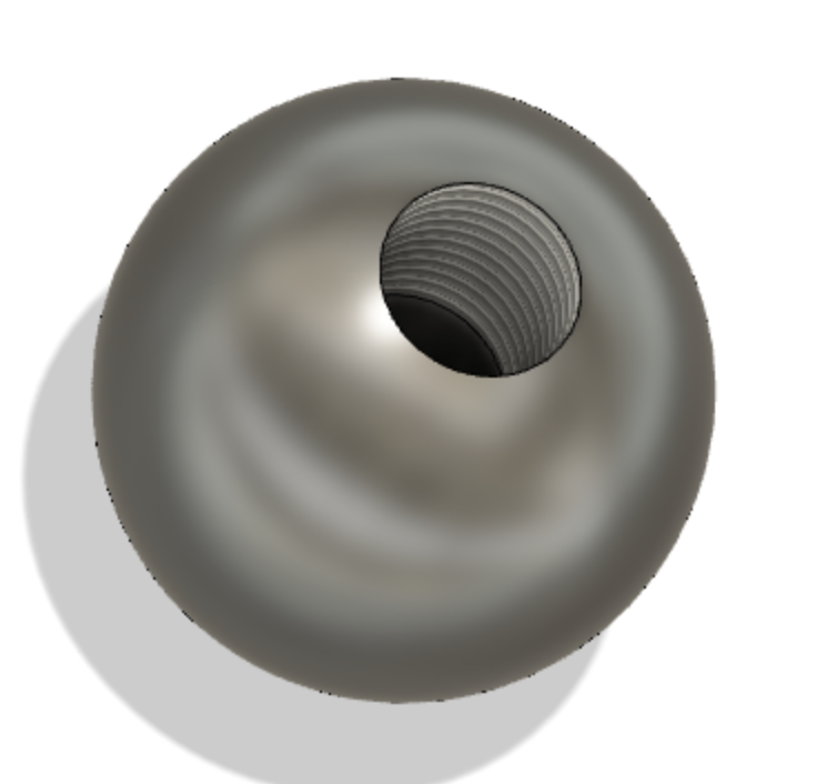
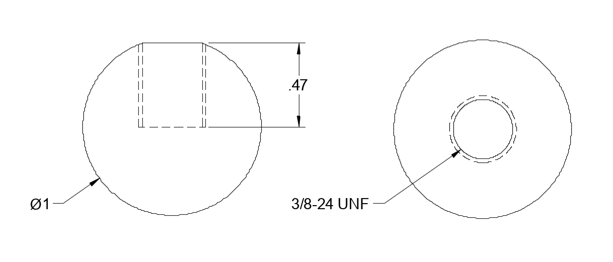
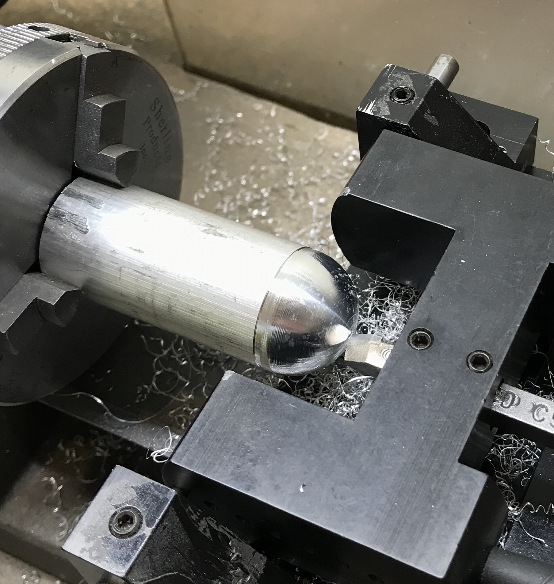
A 2 1/2" length of 1" aluminum rod was cut off and held in the three jaw chuck. It was aligned with a dial indicator. The end was faced. (Too long for this chuck!) The radius attachment was set up and a ball was cut on the end of the shaft. The ball end was center drilled, drilled to "O", and tapped 3/8-24.
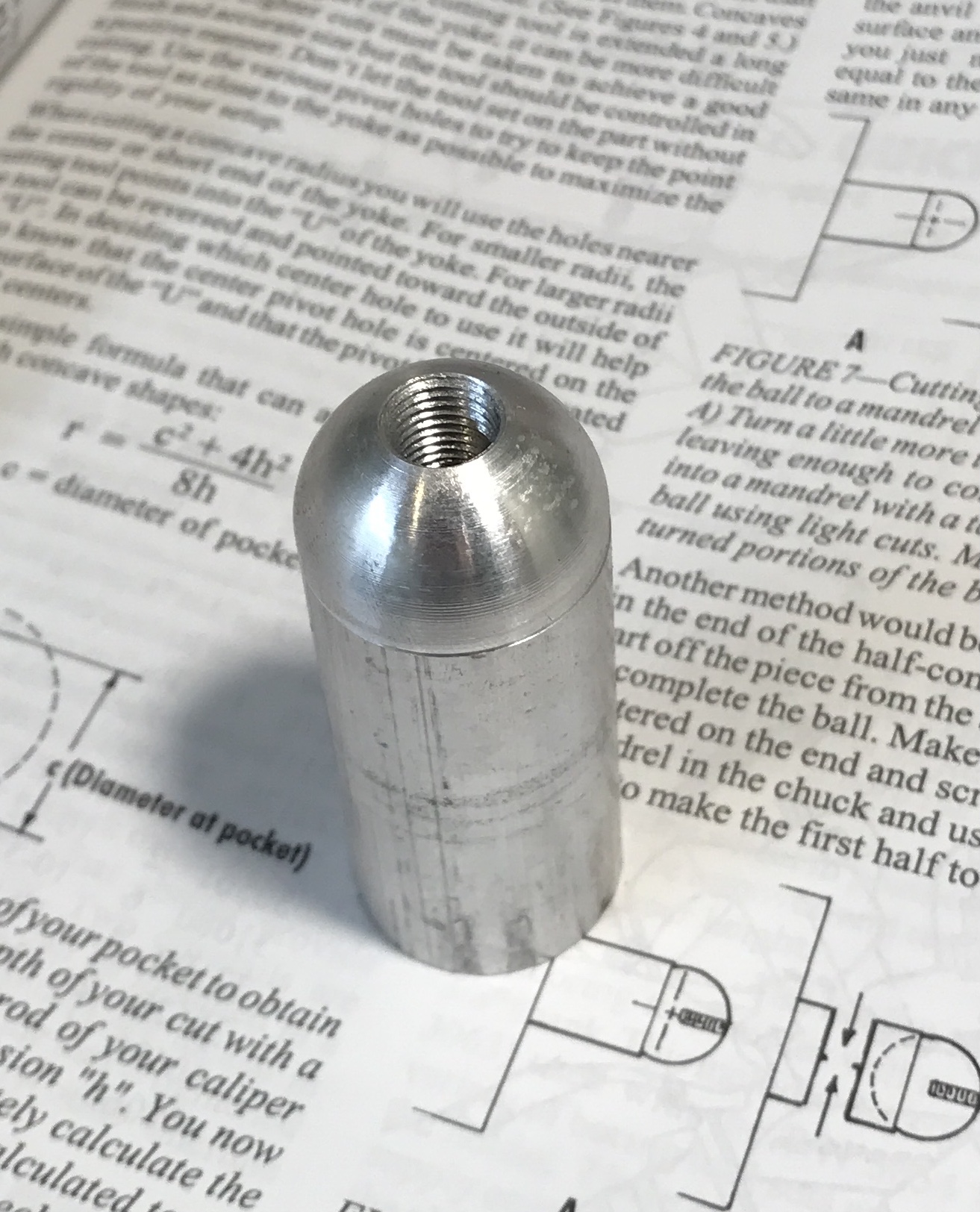
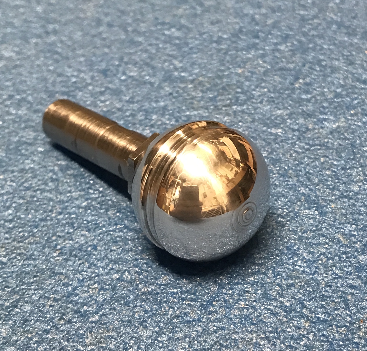
The rod was cut off at 1 1/8" from the drilled end. (Should have cut it closer to size.) The shaft from the gear cutter holder was screwed into the ball end. This was held in the 3/8" end mill collet for cutting the other hemisphere. This proceeded until the 'ball' was more of an elongated ball. As the length was reduced a mistake was made putting a groove in the ball. This became a feature. The ball was sanded to 1500 grit. It was then polished on the wheel with white compound. Finally, a coat of paste wax was applied.
A 1/2" X 1" piece of steel was found in the cutoff bin sized for the pivot. A slightly greater than 1.5" length was cut off with the horizontal bandsaw. This piece was clamped to an angle plate with two machinist's clamps. A square was used to make sure the sawn edge would be cut square. The two flute cutter was used. After a few cuts that chattered and left a poor finish, the two inserts were rotated to new sharp corners. This made a world of difference. The cutting proceeded much more smoothly. After one sawn end was cleaned up the other end was cleaned up and the length reduced to 1.50". Cuts of 0.0075" were used to reduce the length and the final cut was 0.005". Both ends were deburred. The final block of steel is 0.497" X 0.995 X 1.502".
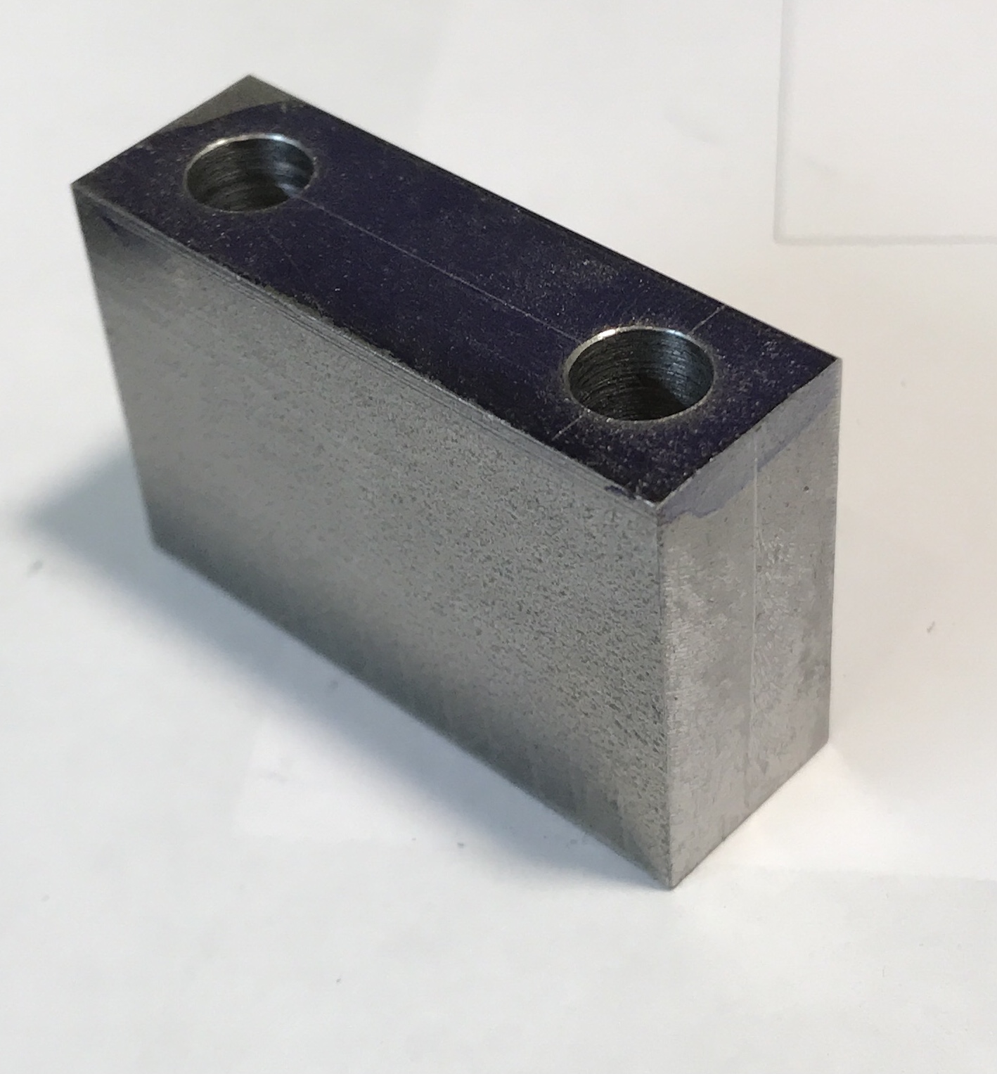
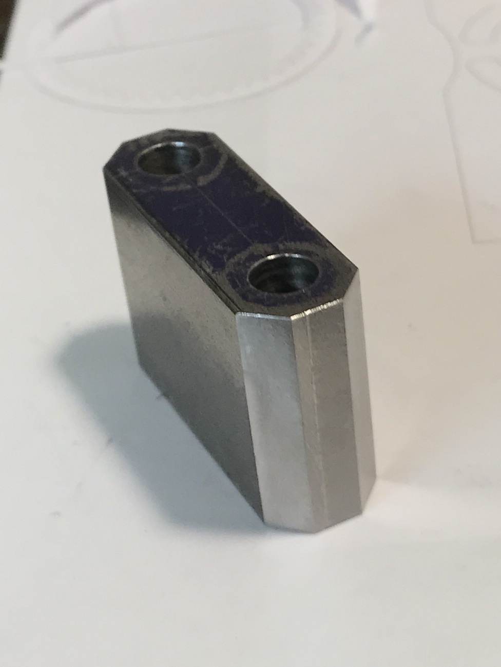
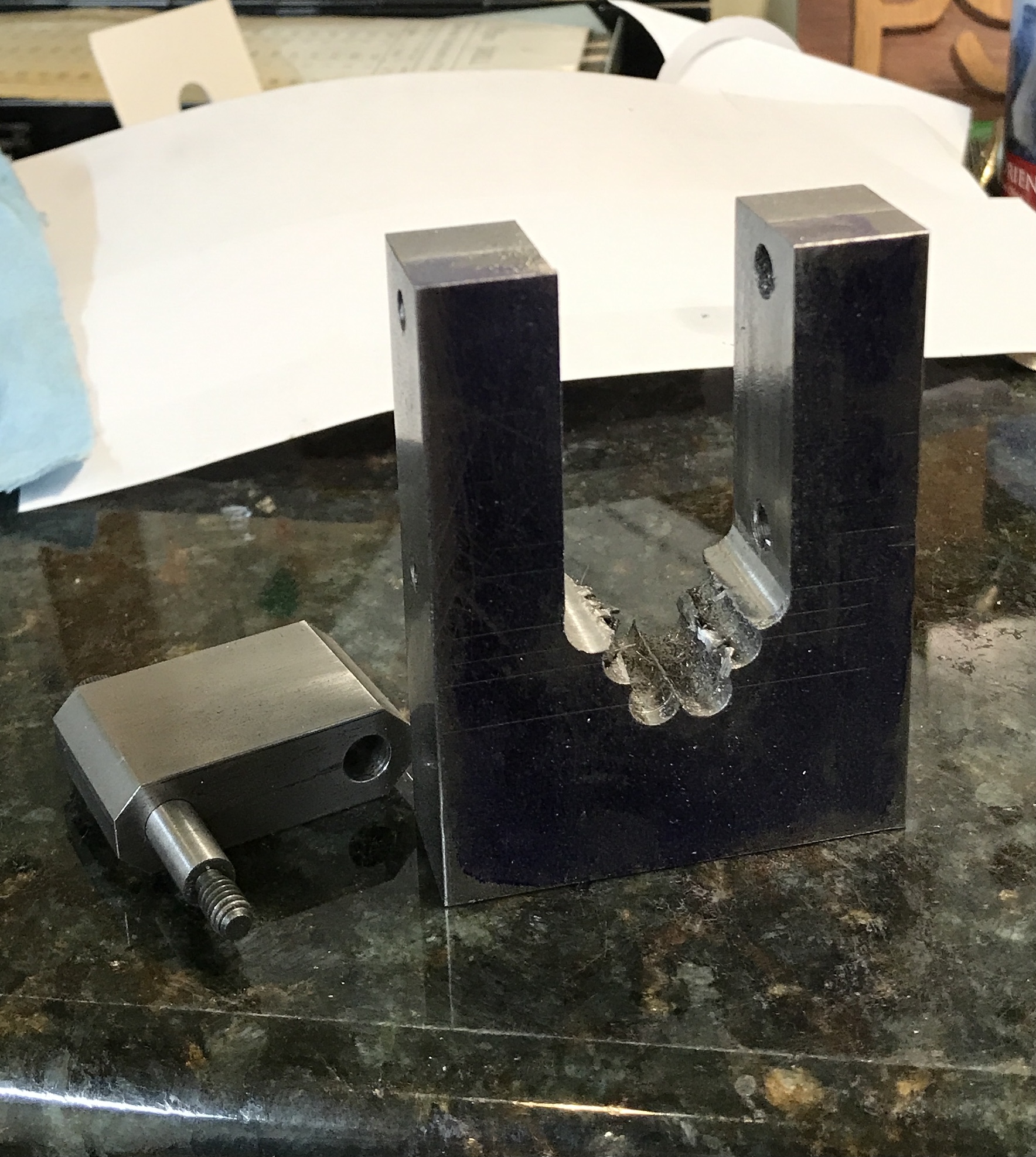
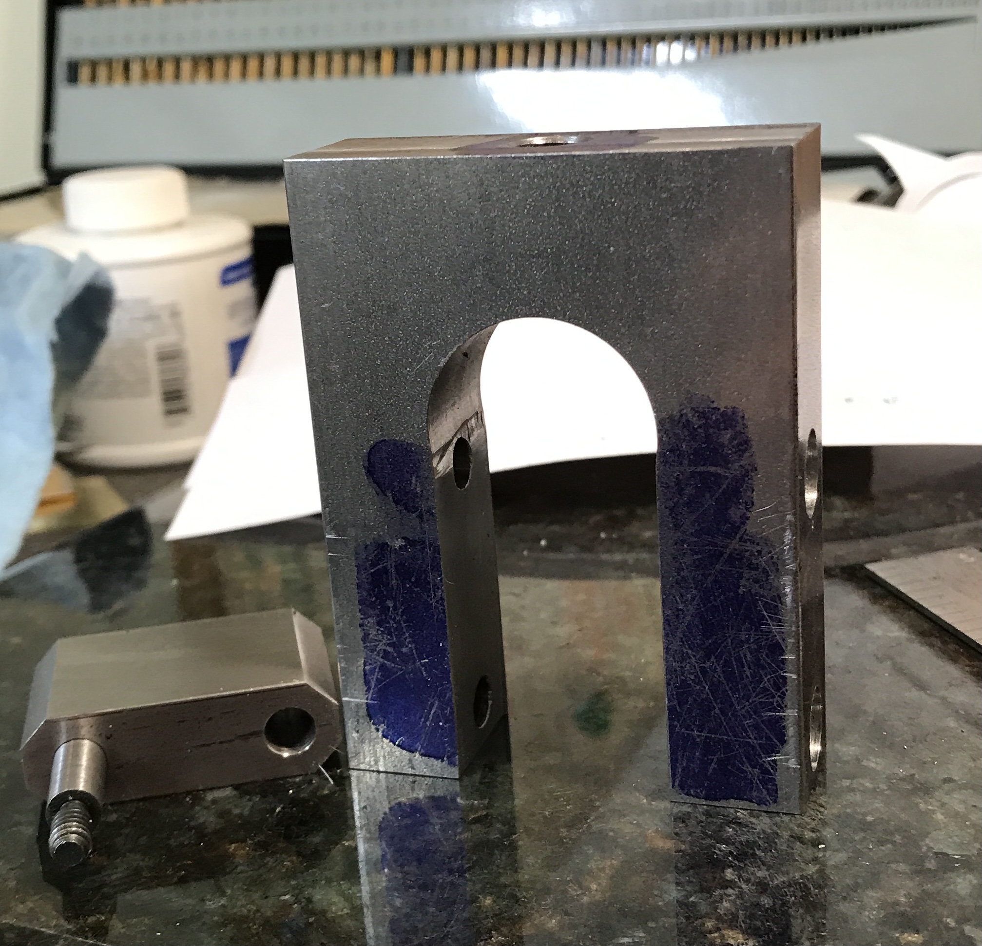
Drilling paralleled the just finished faces. The shorter length should then sit easily between the two tabs on the base. One side (1/2" X 1") was painted with Dykem and marked for two holes on center and separated by 1.000". The holes were aligned with the spotting drill using the slip-on spud. After spot drilling the holes were drilled with a 0.128" drill followed by an "A" drill. The holes were reamed 0.250". The pivot at this stage is shown below.
The next step is cutting a radius on the ends. Prices of radius end mills that cut a 1/4" radius are astronomical. My plan is to make two cuts and leave a semi-octagon, i.e., three faces on the end. A little math was in order. The internal angle of an octagon is (8 - 2)*180/8 = 135°. The side, a, of an octagon as a function of the span, S, or diameter to a side is a = S / (1 + √2). The span is 0.5" so a = 0.207". The height from the current rectangular end to the new face is a/2 = 0.103". So the cut needs to be at a 45° angle and cut to a depth of 0.103".
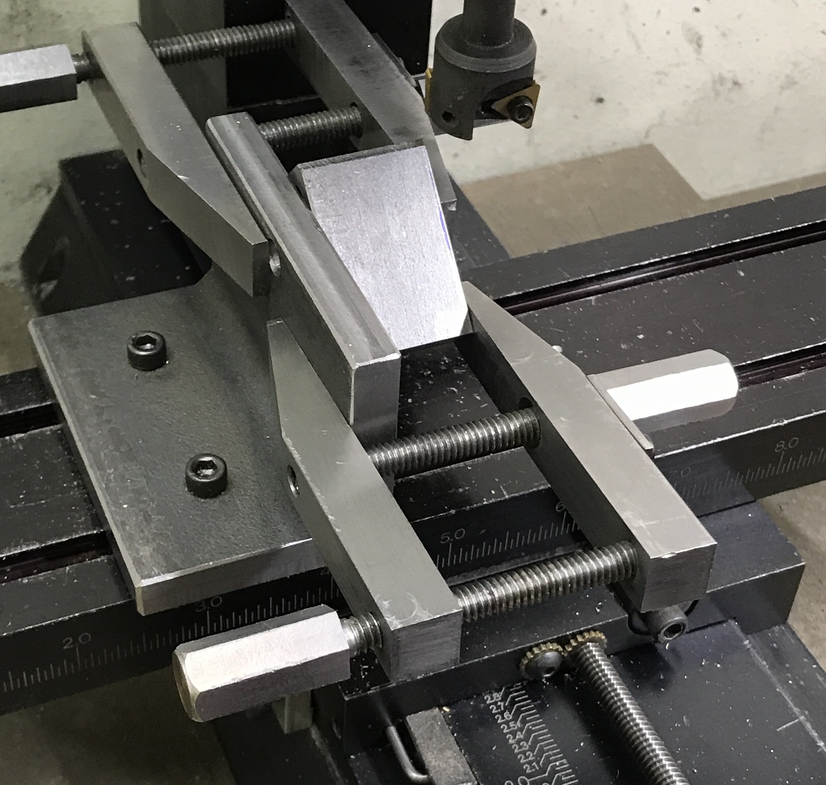
So far I have been unable to hold the part tight enough to mill off the corner. The first attempt was in the vise held on the angle table. The part was held firmly, but the angle table projected the part so high off of the table there was tremendous chatter and poor cutting. The next attempt was positioning it in the vise at a 45° angle. The vise was unable to hold the part tight enough. The third attempt was holding the part against the angle plate with two machinist's clamps. This is shown in the photo below. It is very difficult to get the machinist's clamps aligned for a tight clamp. The part was not held sufficiently rigid.
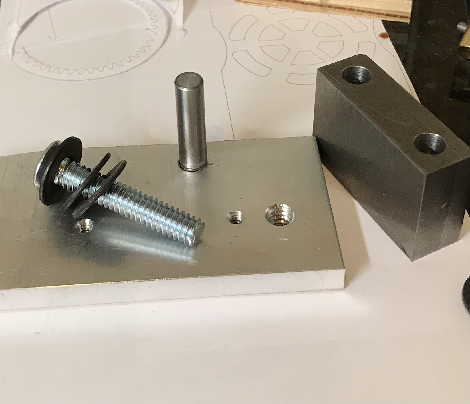
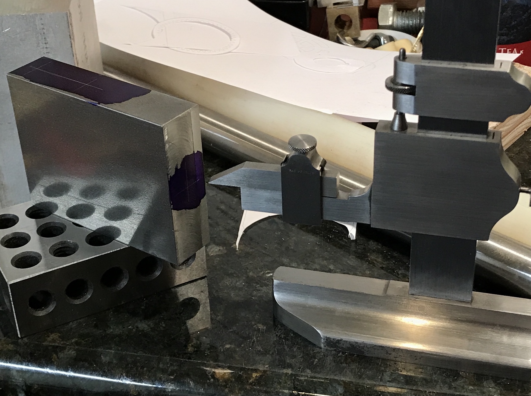
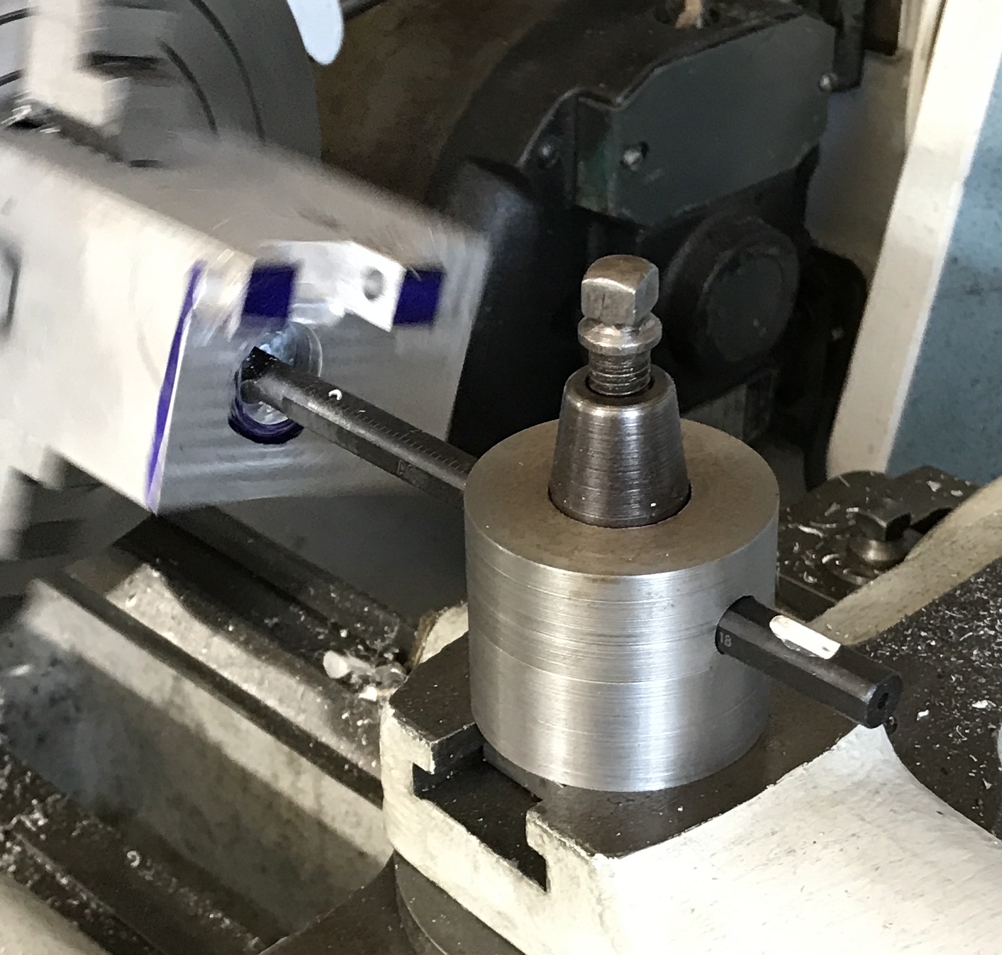
Another approach is making use of the holes. Putting pins or screws through the holes anchored with a jig of some sort might be a more rigid means of holding the part. To this end a scrap of 1/4" aluminum plate was squared up on two sides in the mill. A hole was drilled with a #7 drill and tapped 1/4-20. A 1/4" screw was put through the part and into the tapped hole. The jig was placed against a 1-2-3 block and the part set at 45°. The screw was tightened and the opposite hole was transferred to the jig.This hole was aligned with the spud and spot drilled. This hole was also drilled with a #7 drill followed by tapping. A 1 1/4" length of 0.250" drill rod was cut off and held in the collet in the lathe. One end was faced and the part flipped. The other end was faced and threaded 1/4-20. It was necessary to do the threading in the vise as it was very tough to thread. The photo below shows the finished jig.
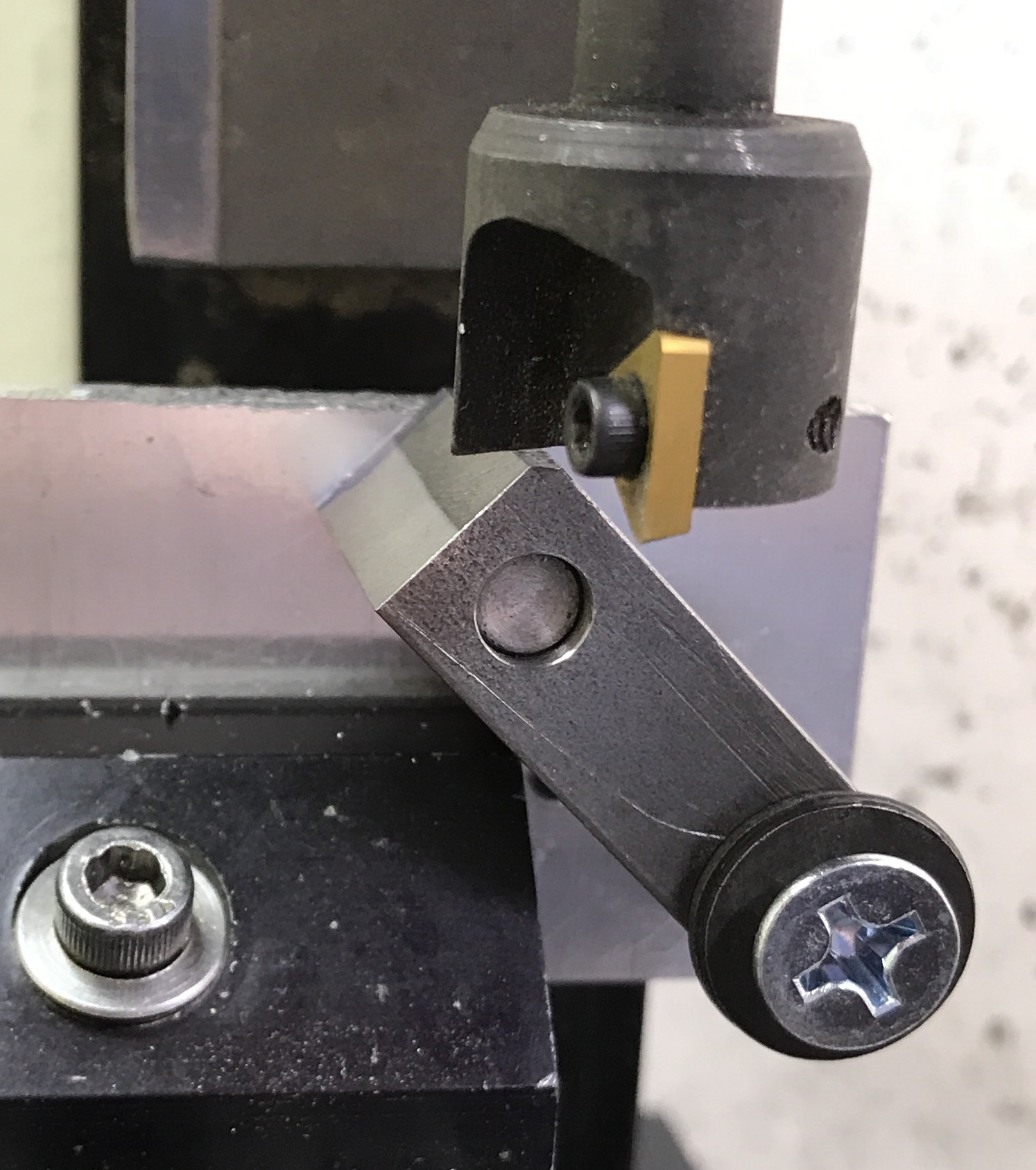
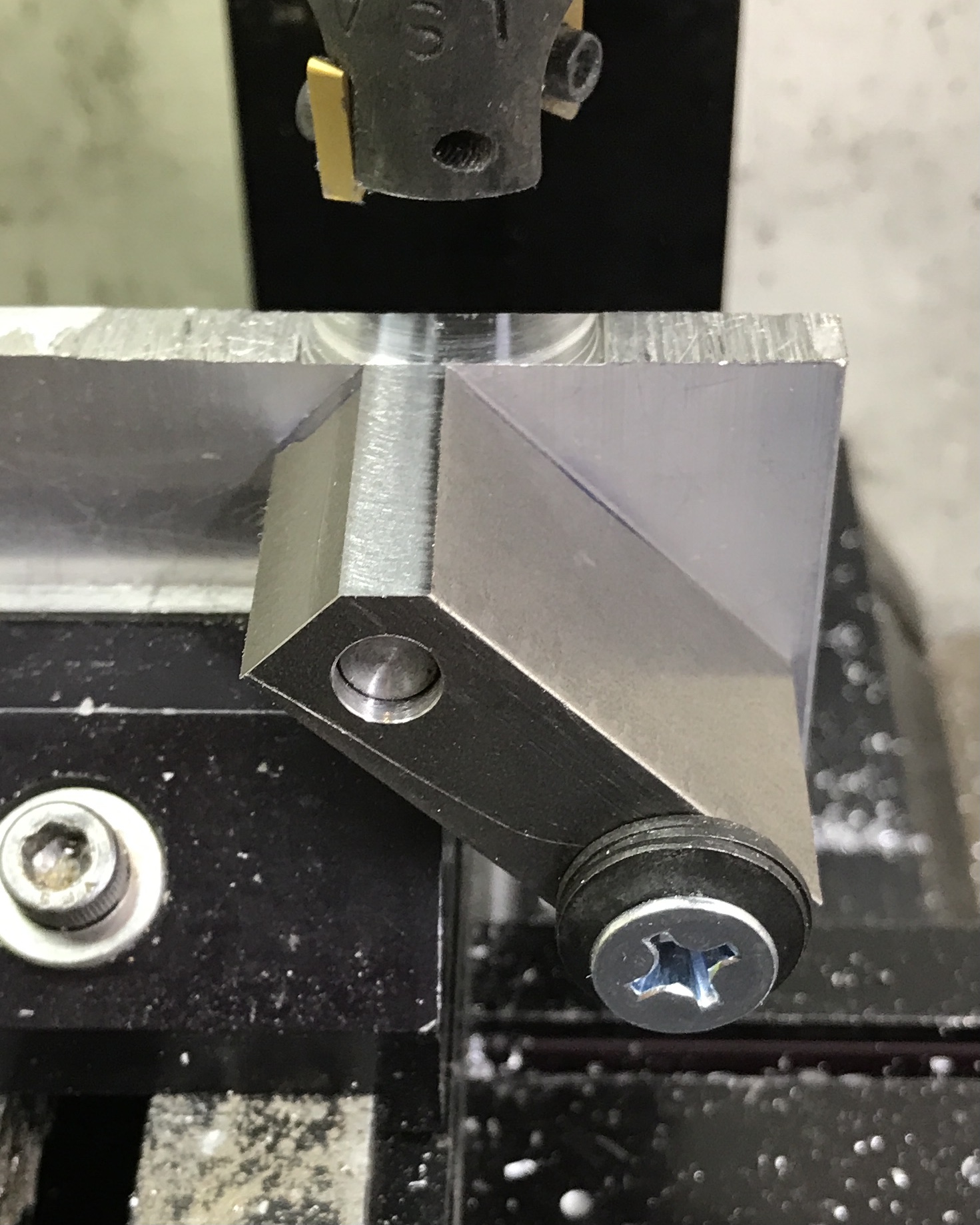
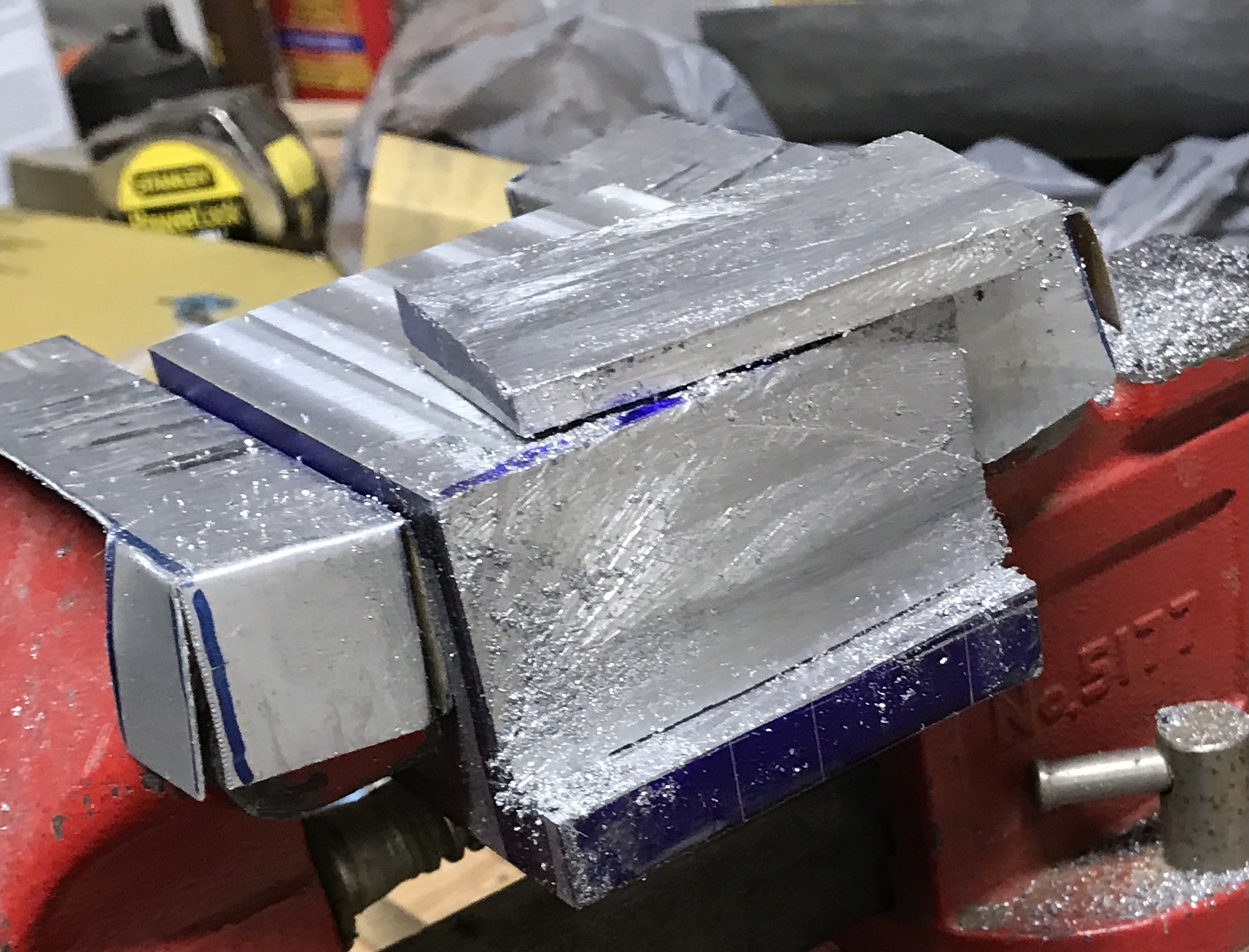
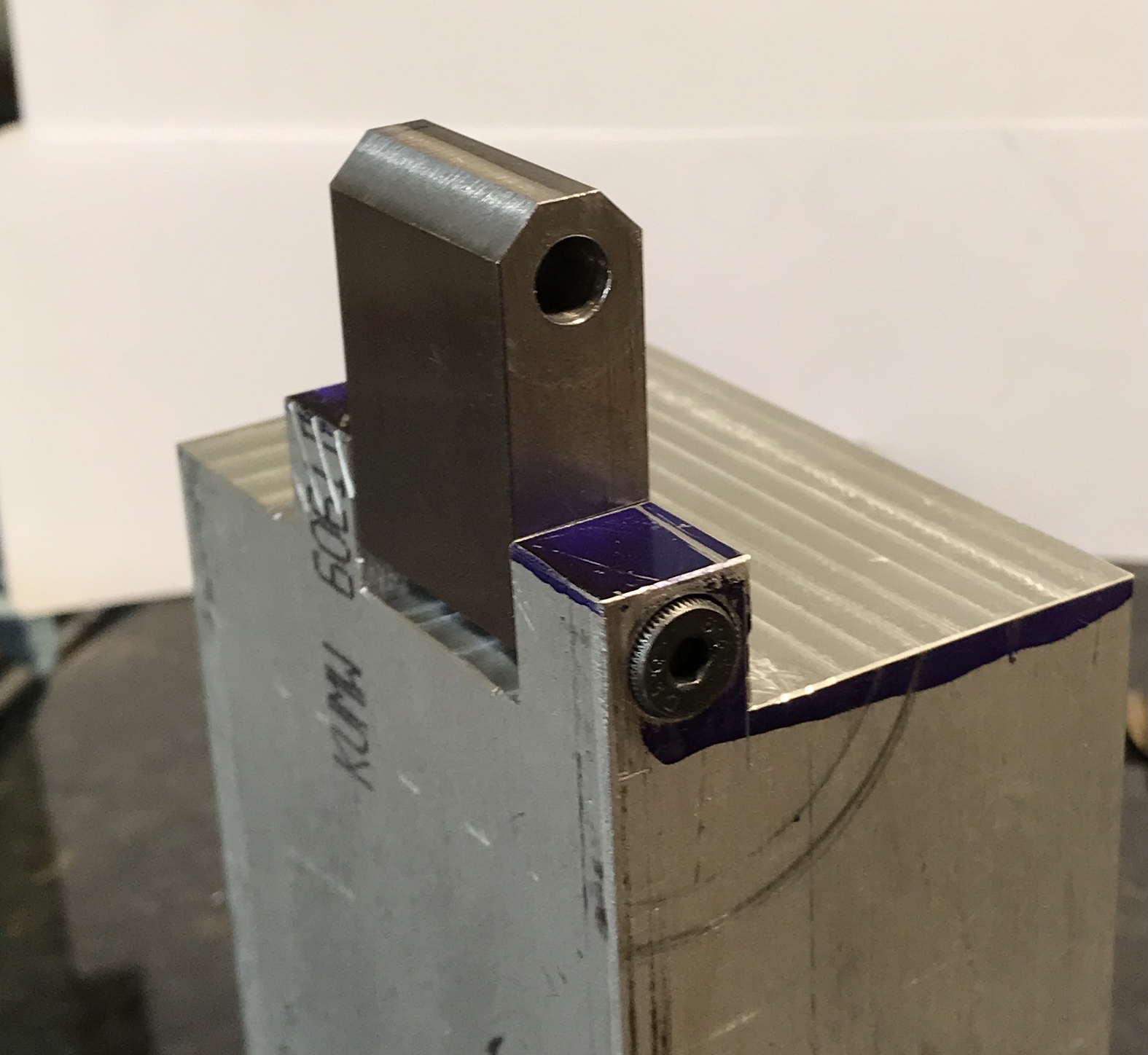
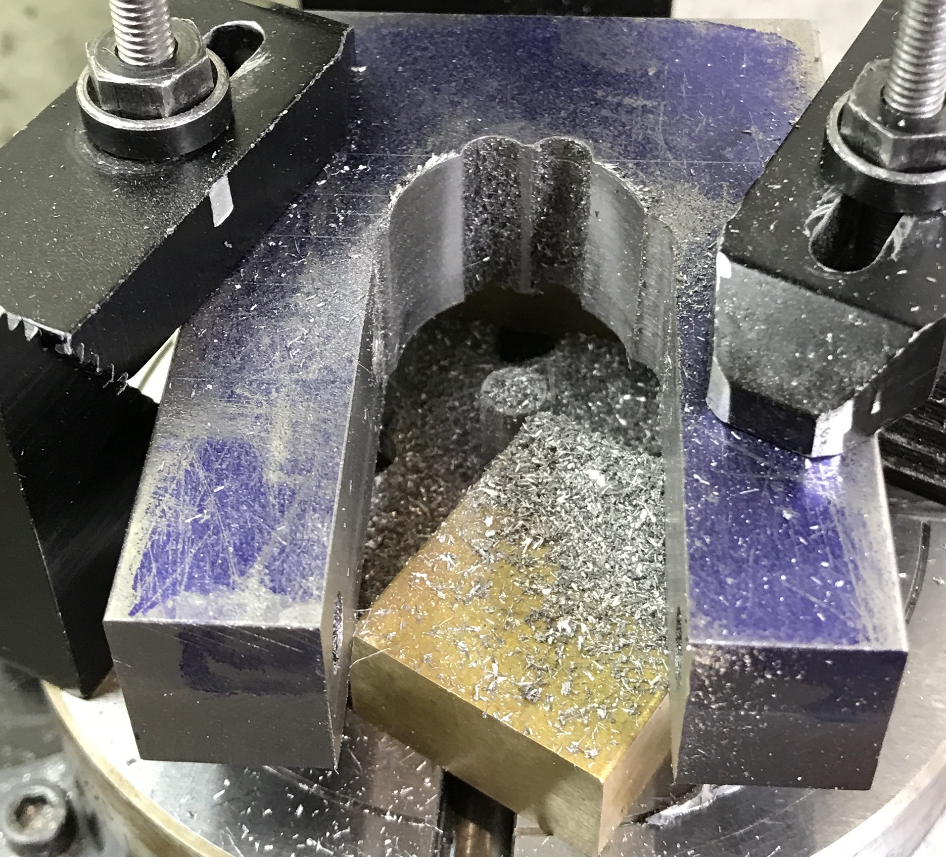
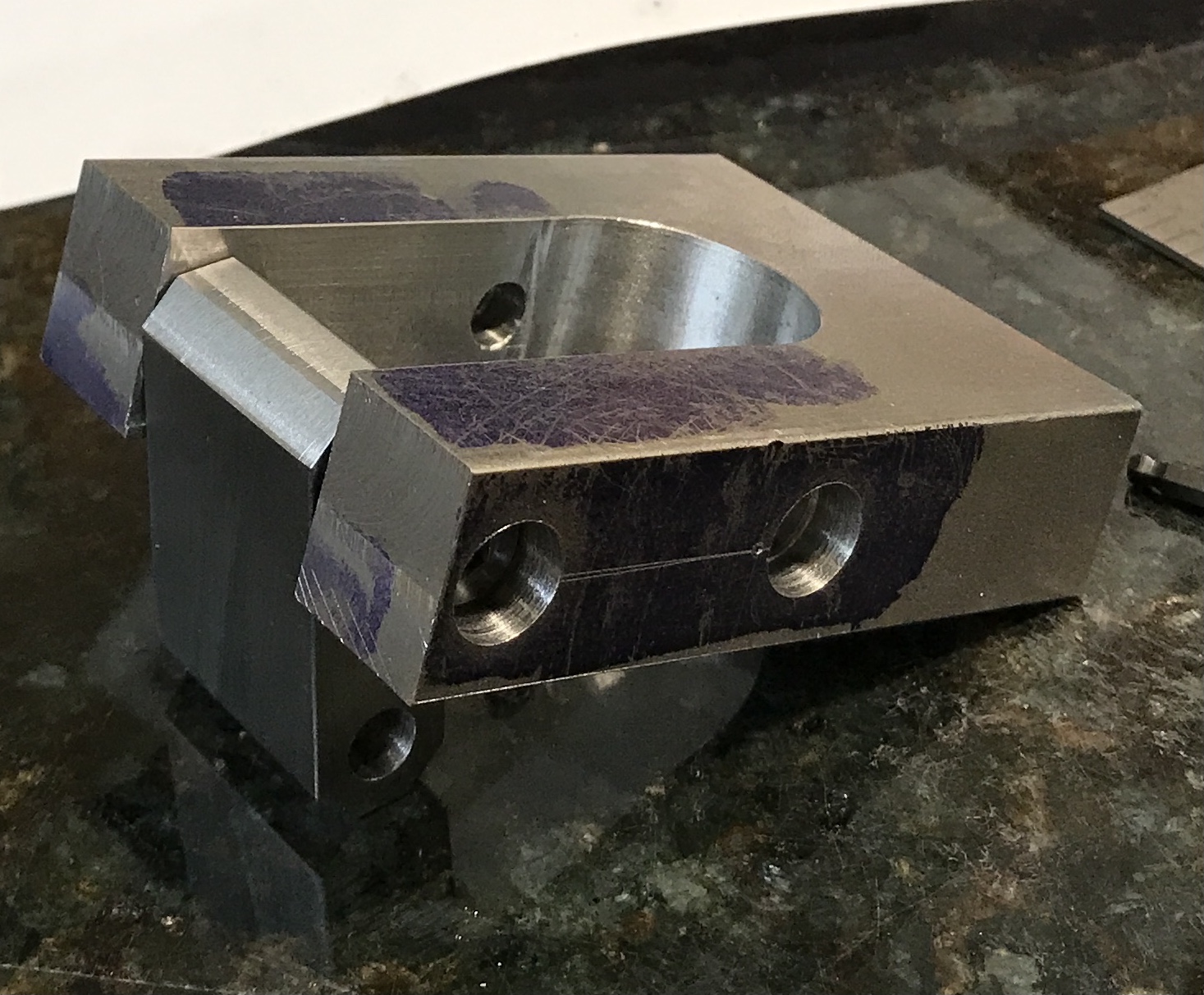
The jig worked like a champ! It held the part as solid as a rock. The first picture below shows the cutting in progress. The flats were cut until the width was about 3/16" + 1/64" or a little over 0.200". This did not correspond with the calculated 0.1" depth of cut. That is probably due to not carefully finding zero on the corner. The first finished octagonal face is shown in the second photo. The last photo shows the completed pivot block. A little sanding cleaned up the uncut faces.
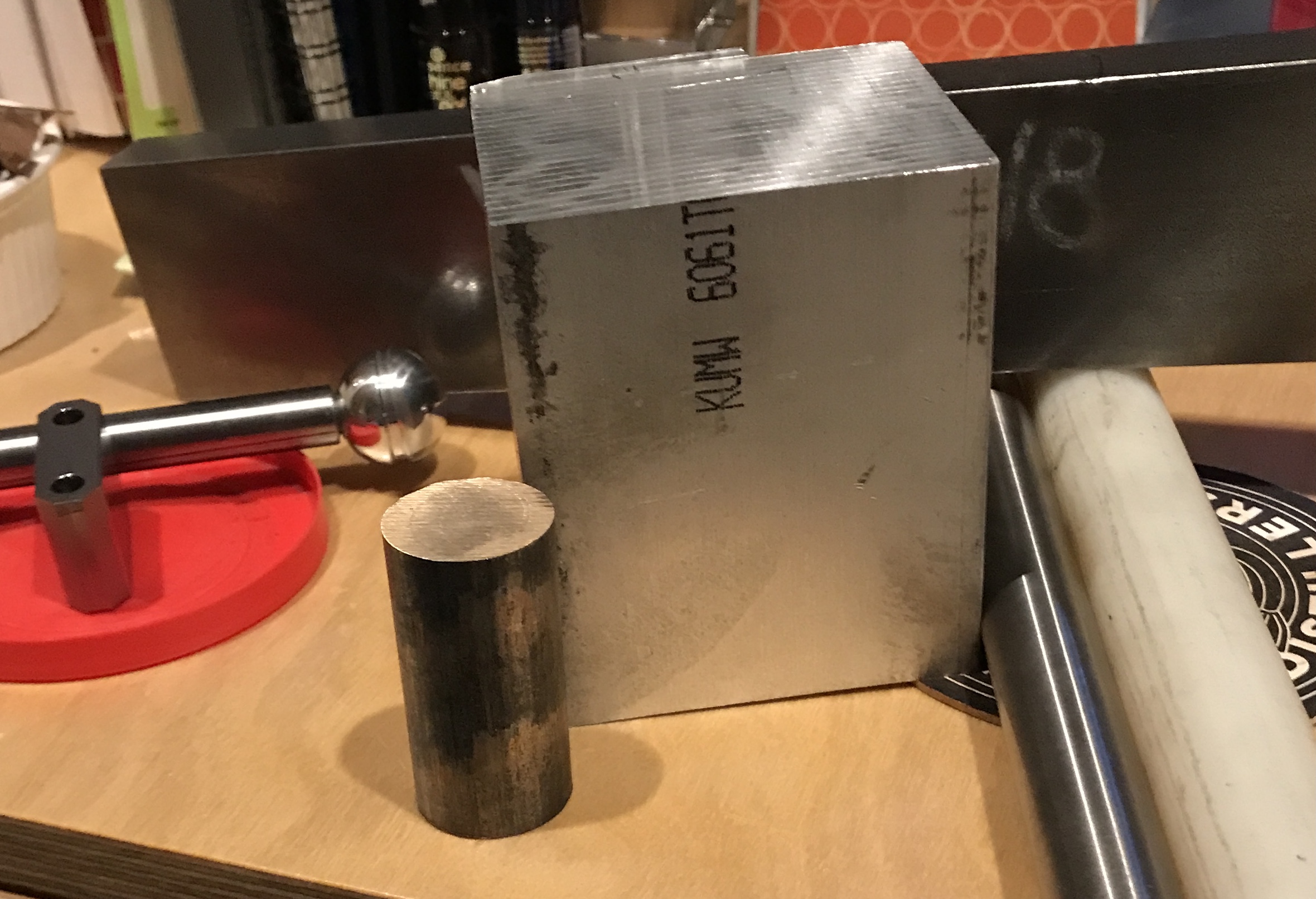
The rest of the raw materials arrived and were opened this morning. The block of aluminum is 3 5/8" long. My call was in time! Still not sure whether to use nylon or bronze for the bushings. I am leaning nylon. There won't be that much wear on these bushings. The large 1018 steel bar is for the yoke. The ram will be made from the turned, ground and polished 1045 steel rod. Not sure when I will get to turning the aluminum block into the base in the cold garage.
The cut ends of the aluminum block are remarkably square as judged by the machinist's square. They have saw marks, but they should easy to clean up in the lathe. Or the shaper if it were working correctly. The yoke will be tackled next. Much of the work can be done in the basement, though it is not clear how best to make the large opening between the legs. The 0.5" radius cutout can be step drilled on the South Bend lathe. Chain drilling should serve well for removing most of the material in the slot. Before any of this is done the holes for the shoulder bolts need to be drilled.
The bar of steel purchased is 0.75" X 2 3/16" not the 2" width ordered. I guess that is why they fudged with ±1/4". A 3" length of the bar was cut off with the bandsaw. The part was held on the angle plate with two machinist's clamps. After squaring the part relative to the table, the top face was cut square with the other sides. The part was flipped over, set on the table and again clamped to the angle plate. The opposite end was squared up with the two insert end mill.
The block is 2.233" wide. The shoulder screws are 2 1/16" long. The threads are 3/8" long and the head is 3/16" long. Shoulder length is 1.50". The arms will be 0.616" wide. A countersink of 0.358" leaves 0.375" for threads on the opposite arm. It should be made a few thousandths less for safety. The block was marked out for the three holes.
The two on the side were tackled first. The punch mark at 0.25" was aligned with the spindle using the spud. The starting drill was used followed by a #25 drill. It was drilled in increments of 0.15" using a lot of cutting fluid. There was no trouble with the drill clogging even when it was 2" deep. The hole was drilled through. It was then widened with a B drill to a depth of 1.858". Then this depth was reamed 0.250". The top of the hole was opened with an O drill followed by a 0.375" drill to a depth of 0.25". A 0.375" end mill was used to produce a flat-bottomed hole 0.350" deep. This sequence of events was repeated a further 1.25" from the first hole. Again a lot of cutting fluid was used throughout the process. The last 3/8" of hole was tapped 10-24 from the side opposite the drilling as the tap was not long enough to follow the drill. After cleaning out the chips a shoulder bolt fit nicely in the two holes.
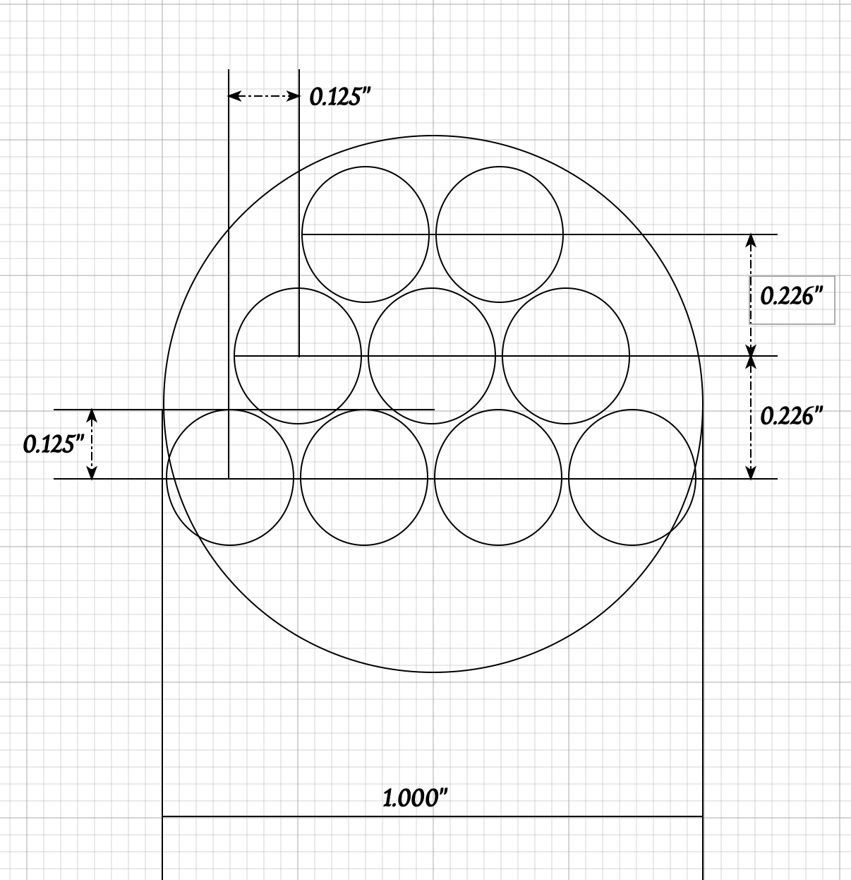
The best way I have come up with to cut the round ended slot in the yoke starts with drilling. The picture below is a rough sketch of the drilling needed to rough out the semicircle. If an "A" or a "B" drill is used there should be sufficient webbing between holes so the drill does not wander. Final clean up would take place on the rotary table. Before starting that the hole for the handle was drilled up to "O" and tapped 3/8-24. The handle fits well, but the threads on the handle are a little long.
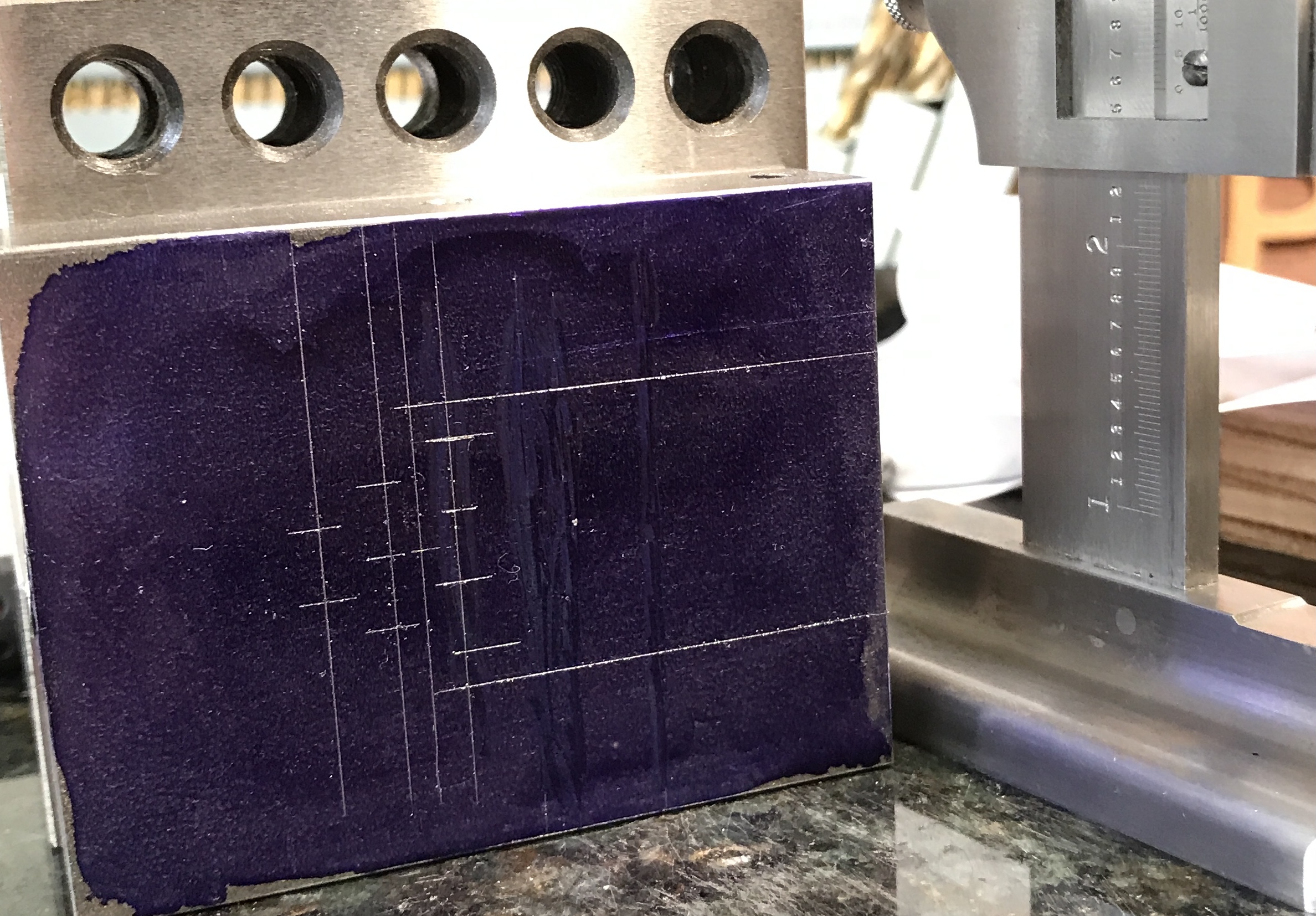
Due to the oversize part the edges of the slot are 0.616" from the edge of the part. Consequently, the four holes below the semicircle center line are centered at 0.741", 0.991", 1.241", and 1.491". These same holes are aligned 1.75" - 0.125" = 1.625" from the open end. (My part is not 3.5" long, only 3.0".) The second line of holes are aligned at 1.625" + 0.226" = 1.851". Their centers from the edge are 0.866", 1.116", and 1.366". The third line of two holes are aligned at 2.077" and the two hole centers are 0.991" and 1.241" from the edge. The photo below shows the marked out hole centers plus the center of the 1" diameter arc.
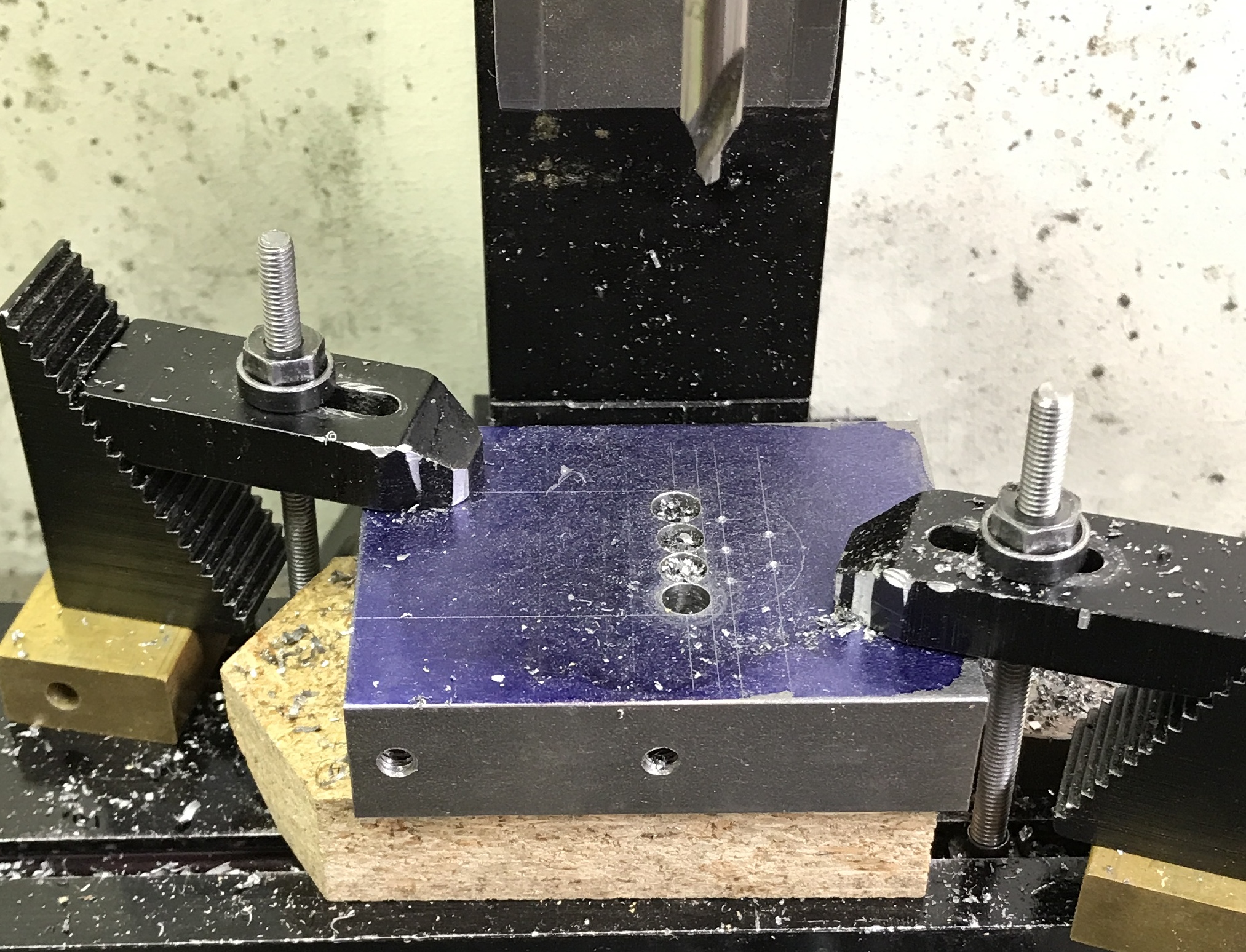
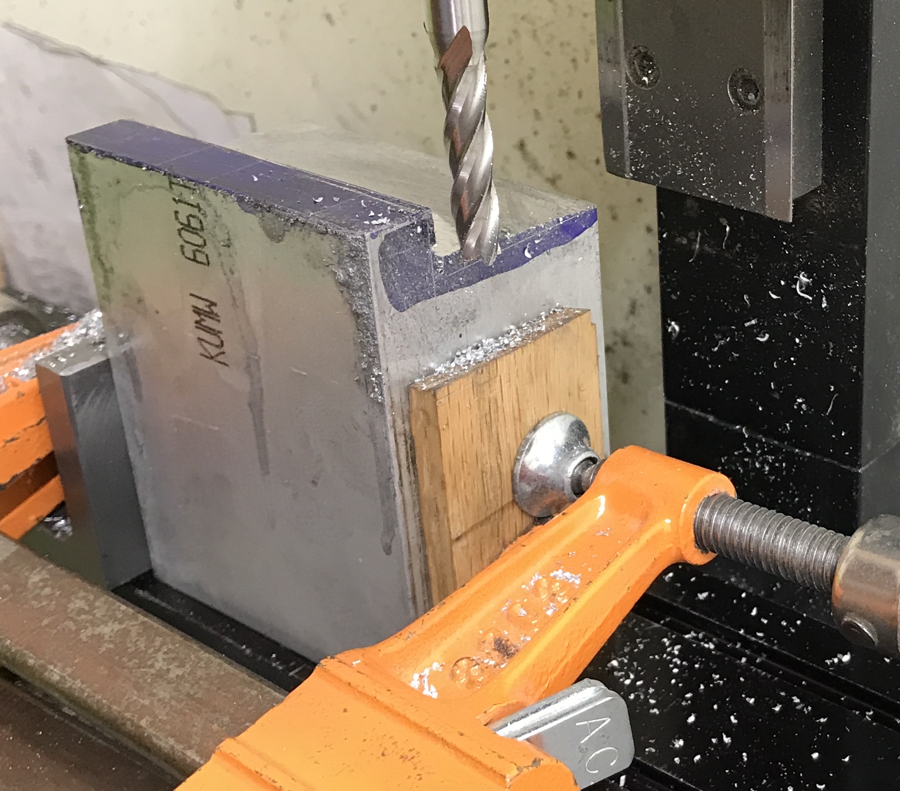
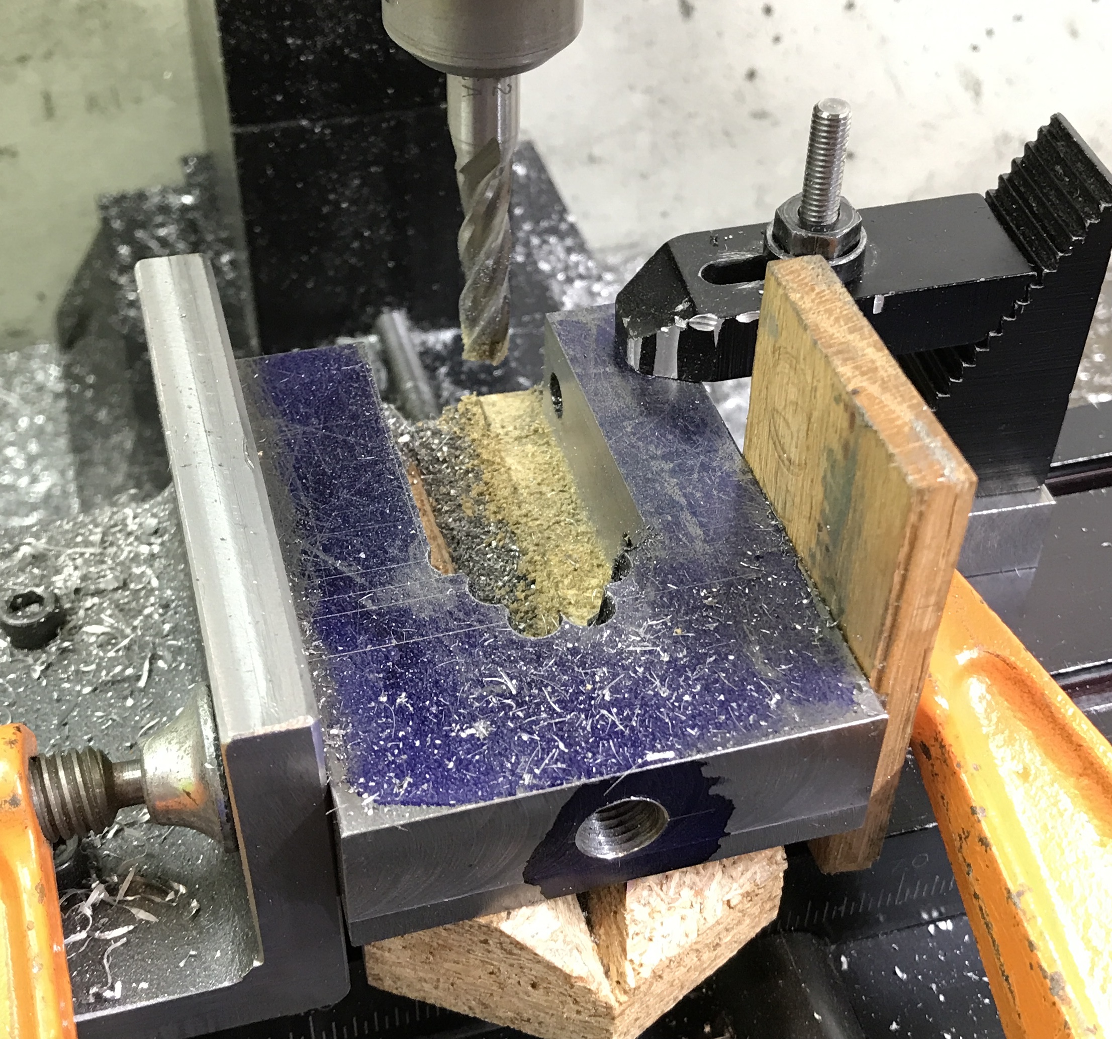
The yoke was held on a block of wood with two strap clamps. A center drill was aligned over the first of the holes in the four hole row. It was center drilled, and then drilled with the "A" drill. (The "B" drill was dull.) Oil was applied liberally when chips were cleared. All nine holes were drilled in this way as shown in the photo.
The yoke with the drilled holes was held in the vise. The hacksaw was used to cut down both sides of the opening to the holes. It was quite the right arm workout. The scrap piece was knocked out with a hammer producing the roughed out yoke. The final shot shows the yoke ready to be milled along with the center scrap.
It is supposed to be unseasonably warm today. It is 45° now and going up to 55° this afternoon. The body will be tackled. The ends need to be cleaned up and squared. The main hole needs to be drilled and bored for the bearings. I might also do some milling on the yoke using the milling attachment on the South Bend lathe.
The block of aluminum purchased is 2.5" X 3" X 3.6", while the plans are for a block that is 2" X 2.75" X 3.5". The 3" versus 2.75" is not a problem. I can either face it off or leave it be. the dimensions for all of the features relying on this dimension are not impacted if they are all marked out from opposite faces. The challenge is the 2" versus 2.5" dimension. I might try removing the bulk of this with the bandsaw. Leaving it at 2.5" would just entail extra material hanging off the right side when mounted. The band saw is needed to cut off the waste at the top to leave the two protruding tabs.
The block was marked at 2" and cut off with the band saw. The cut was not very straight, but luckily it was left oversized on one side, about 1/8". The block was held against the angle block with a bar clamp. The top was milled with the two flute cutter until it was flat and down to the 2" line. A 0.003" cut was made to leave a nice finish.
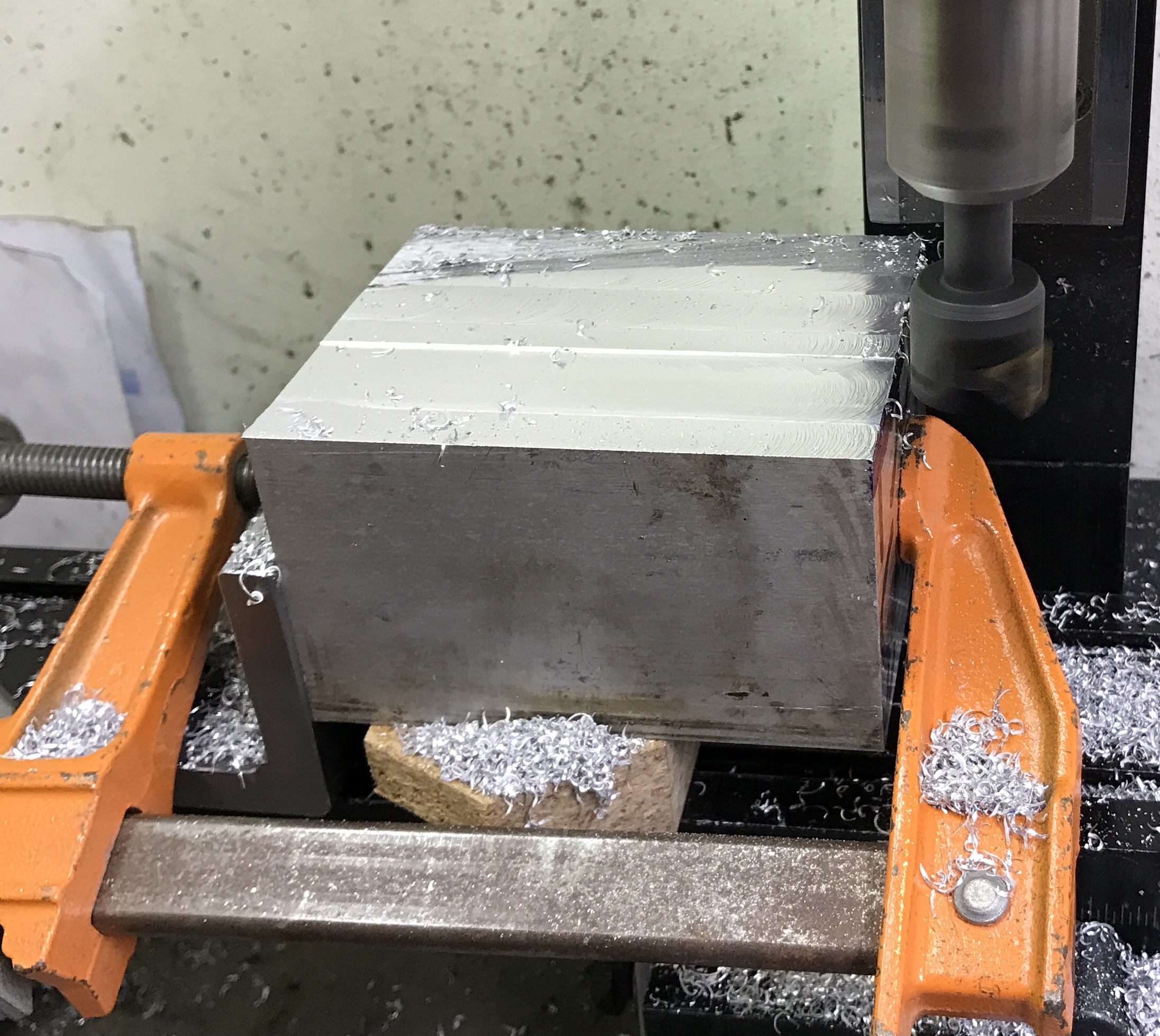
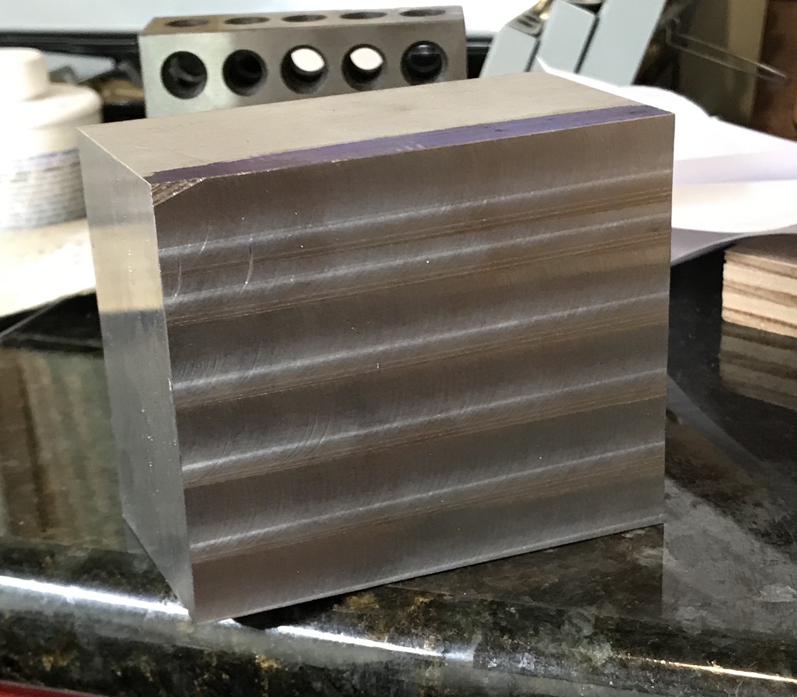
The block was turned and one of the cut ends was similarly milled till flat and finished nicely. The block was flipped end for end and the opposite cut end was also milled flat.
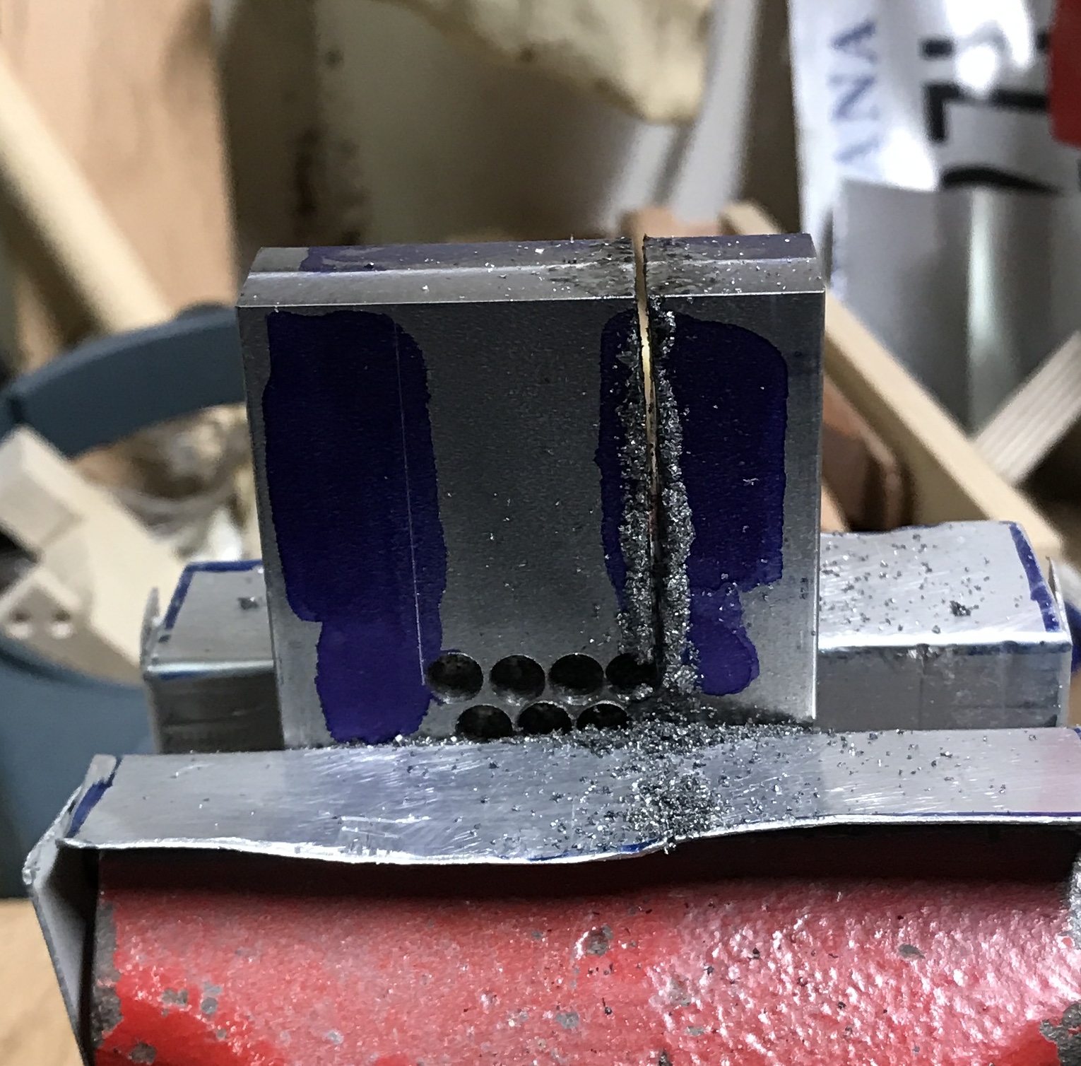
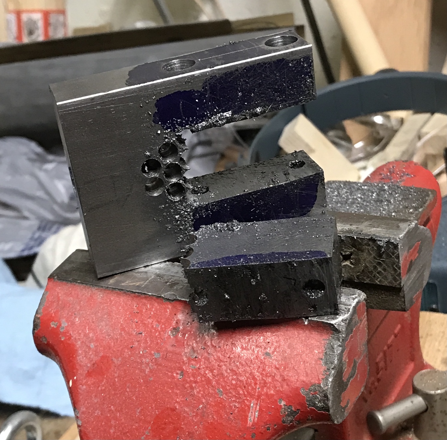
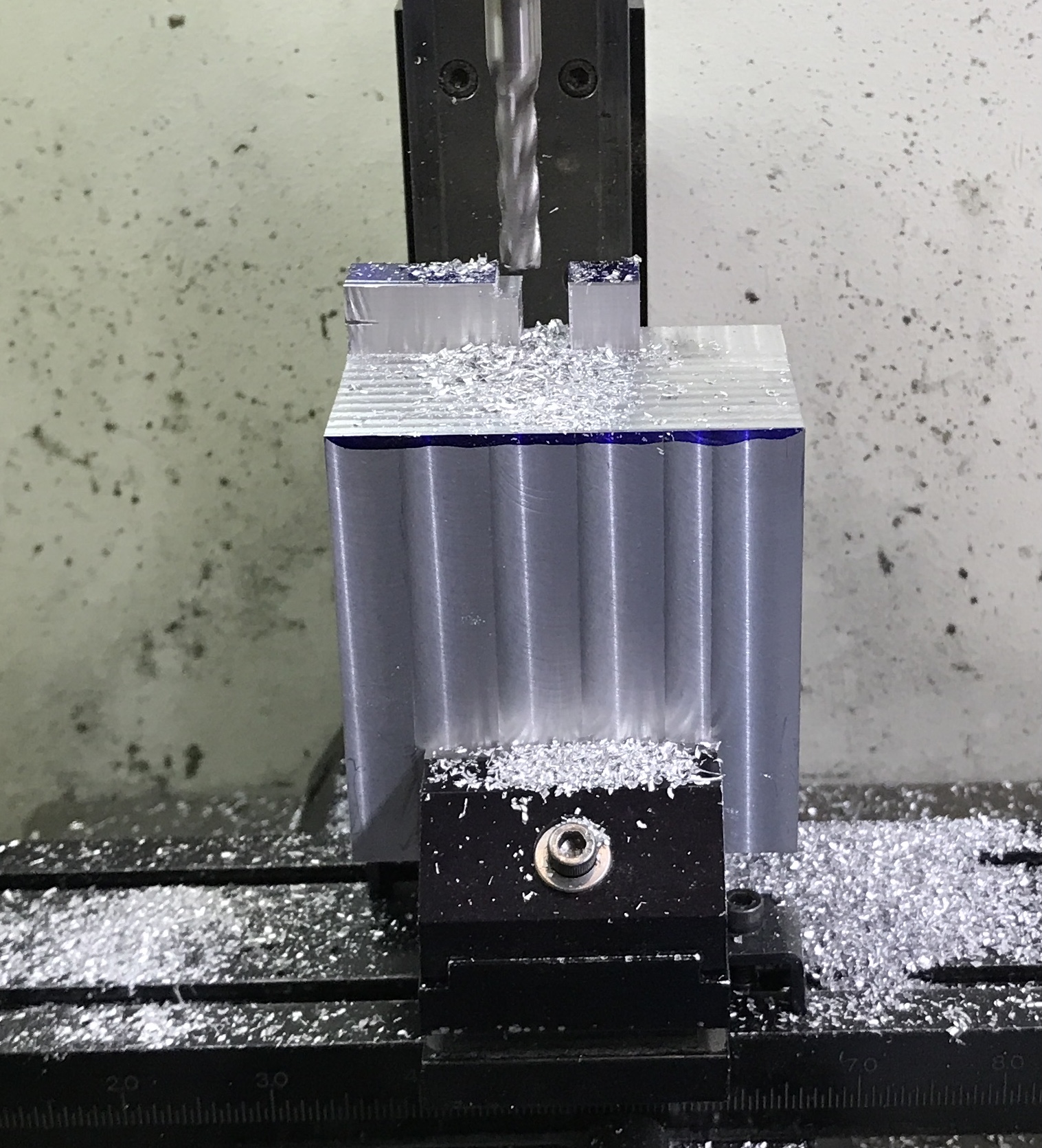
After a bit of milling, 5/16" end mill at 0.031" depth and 0.150" wide cut, I decided to remove the bulk of the material with a hack saw. The top was marked out to denote the two 0.5" X 0.5" X 0.5" tabs. A saw cut was made parallel to the two tabs down to almost 0.5". Starting from the opposite side of the tabs the top was sawn down to the previous saw kerf. This took one full hour of hard hack sawing! The block was set up in the mill with two clamps holding it against the angle plate. The pretty crooked saw cut was cleaned up with many passes of the 5/16" end mill. The second photo shows the clean up in progress. This left one side 1/2" high and 1/2" wide for the two tabs.
The next step was freeing the tabs. The raised part beyond the middle tab was removed first. It was cut in 0.050" X 0.150" increments with the 5/16" end mill. The milling went surprisingly well considering how much material was being removed and the distance from the vise to the cutting point. The area removed was milled to match the depth of the top surface. The face of the tab was climb milled 0.005" for clean up.
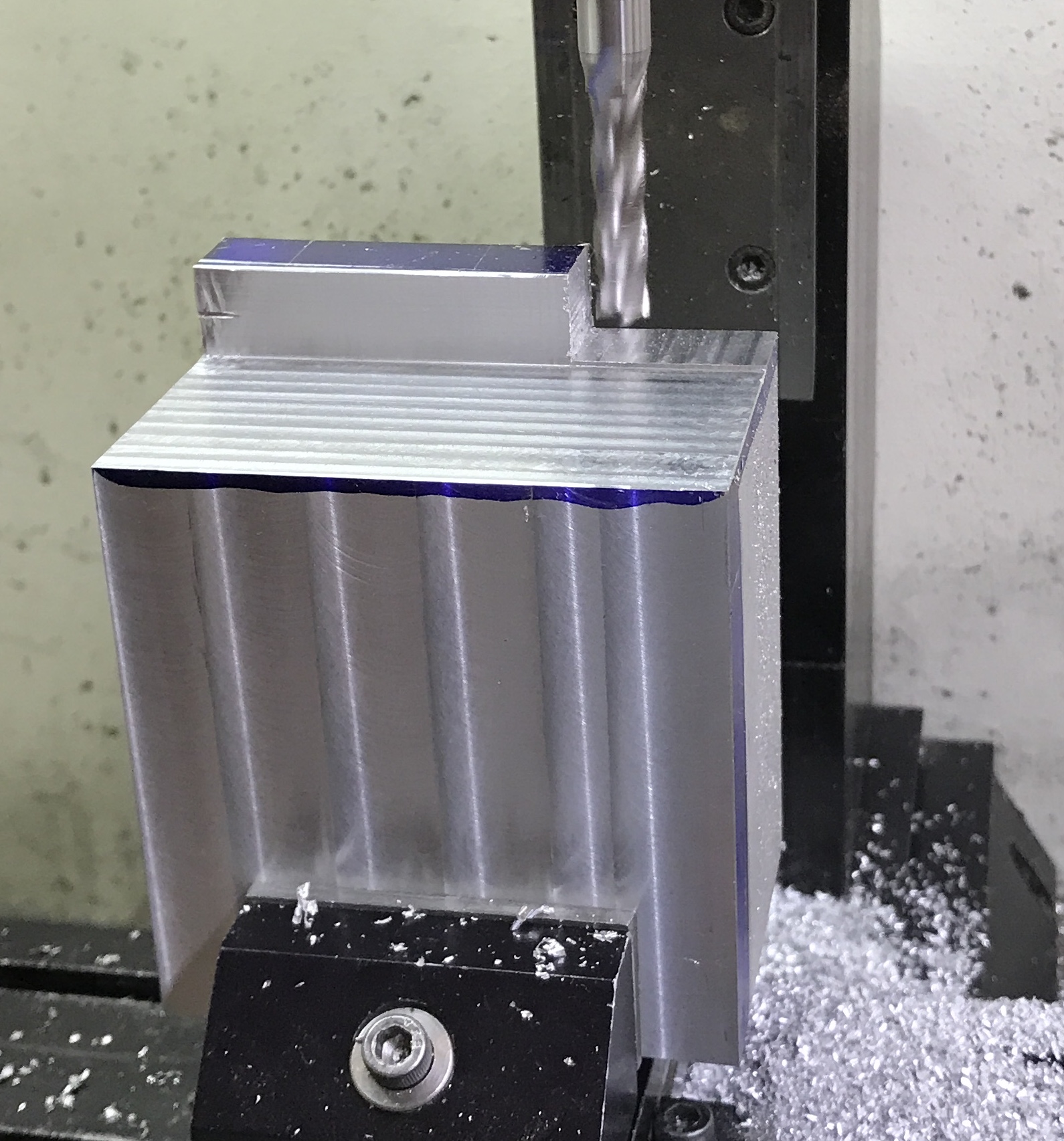
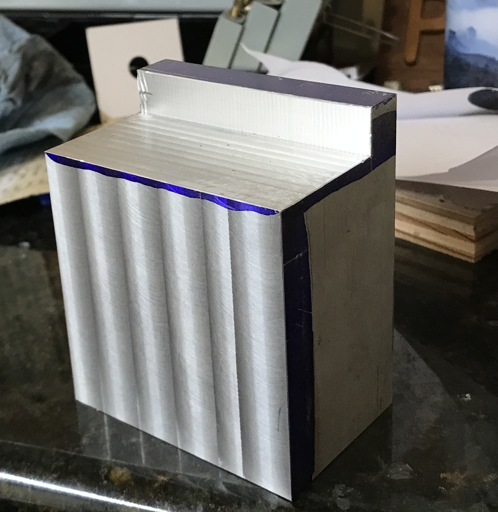
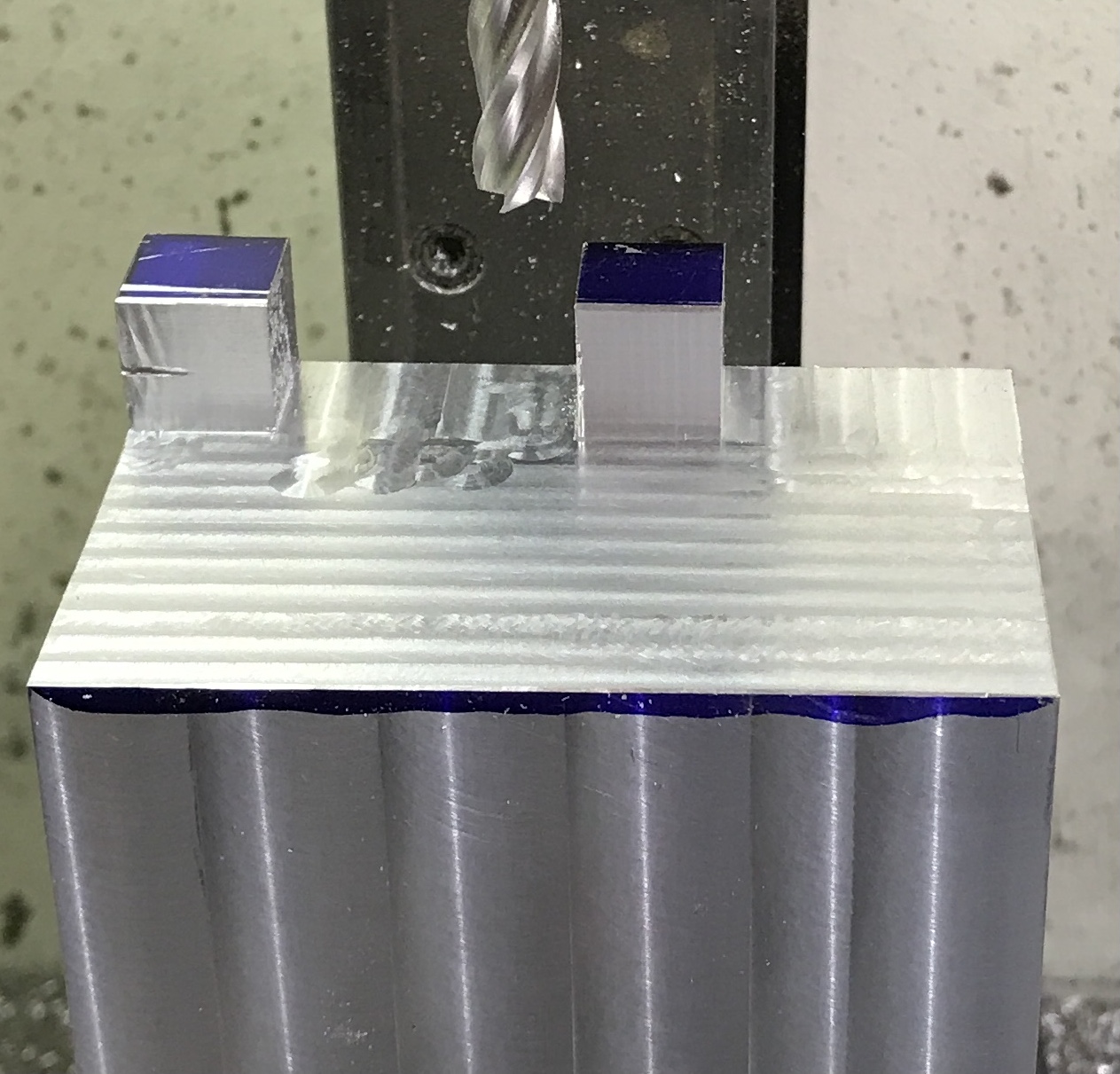
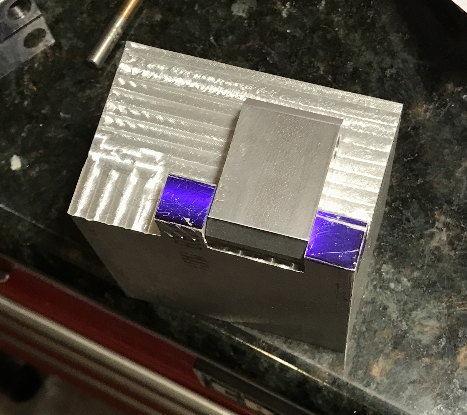
The material between the tabs was removed similarly. The first cut was at full end mill width and was only 0.025" deep on each pass. The first photo below shows the cutting in progress and the second is finished.
The pivot is a nice fit between the tabs.
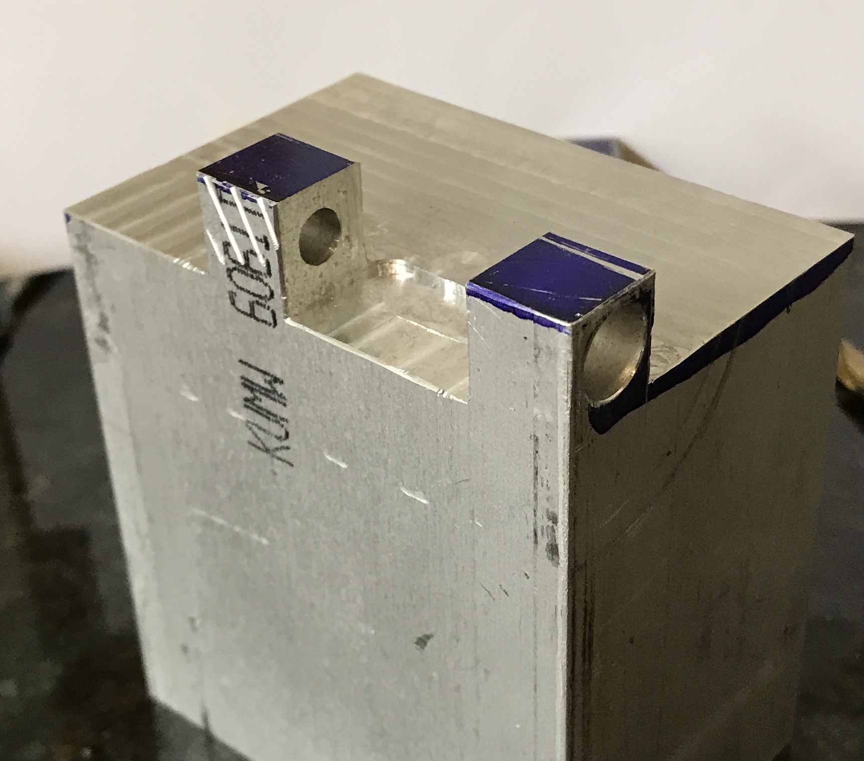
The block of aluminum was again set up on the milling table clamped to the angle plate. The end tab had been marked on center for the hole. A #25 drill was used to drill through both tabs. This was followed by the "A" drill to a depth of 0.30" in the second tab. A 0.250" reamer was used to make a perfectly round hole. Finally, a 3/8" end mill was used to make the counterbore 0.30" deep. The shoulder bolt fit smoothly, but not when the pivot was inserted between the tabs. The hole was not far enough from the top face of the block. The area between the two tabs was milled 0.050" deeper. The pivot now fits with room to spare when rotated.
The body still has a number of features that need to be made. There is a hole for mounting and a matching hole for a set screw. The main hole needs to be drilled through and the ends need to be bored for the bearings. The bearings then need to be bored in place. The yoke needs to have the opening widened to 1". The yoke also needs to have the semi-circular opening milled on the rotary table.
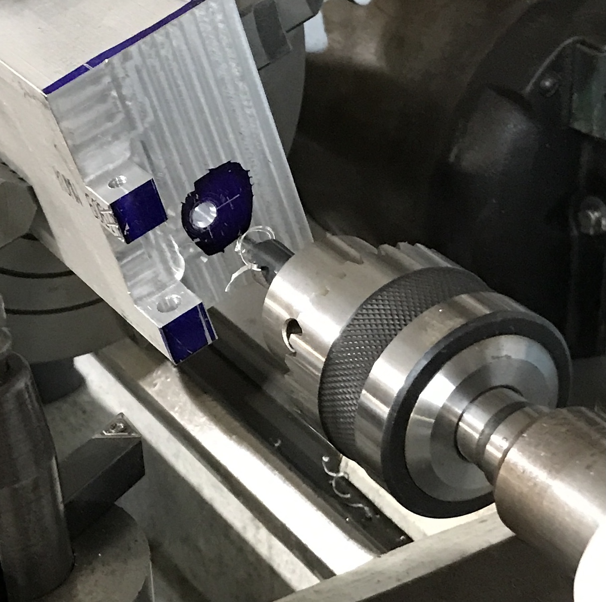
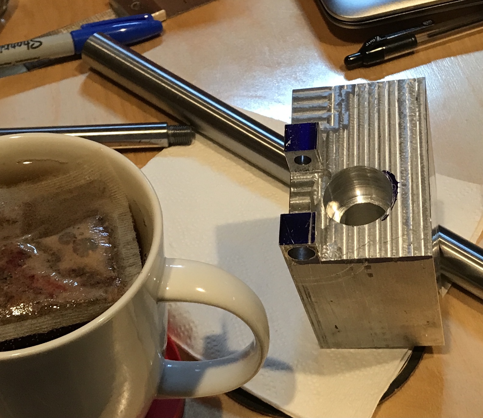
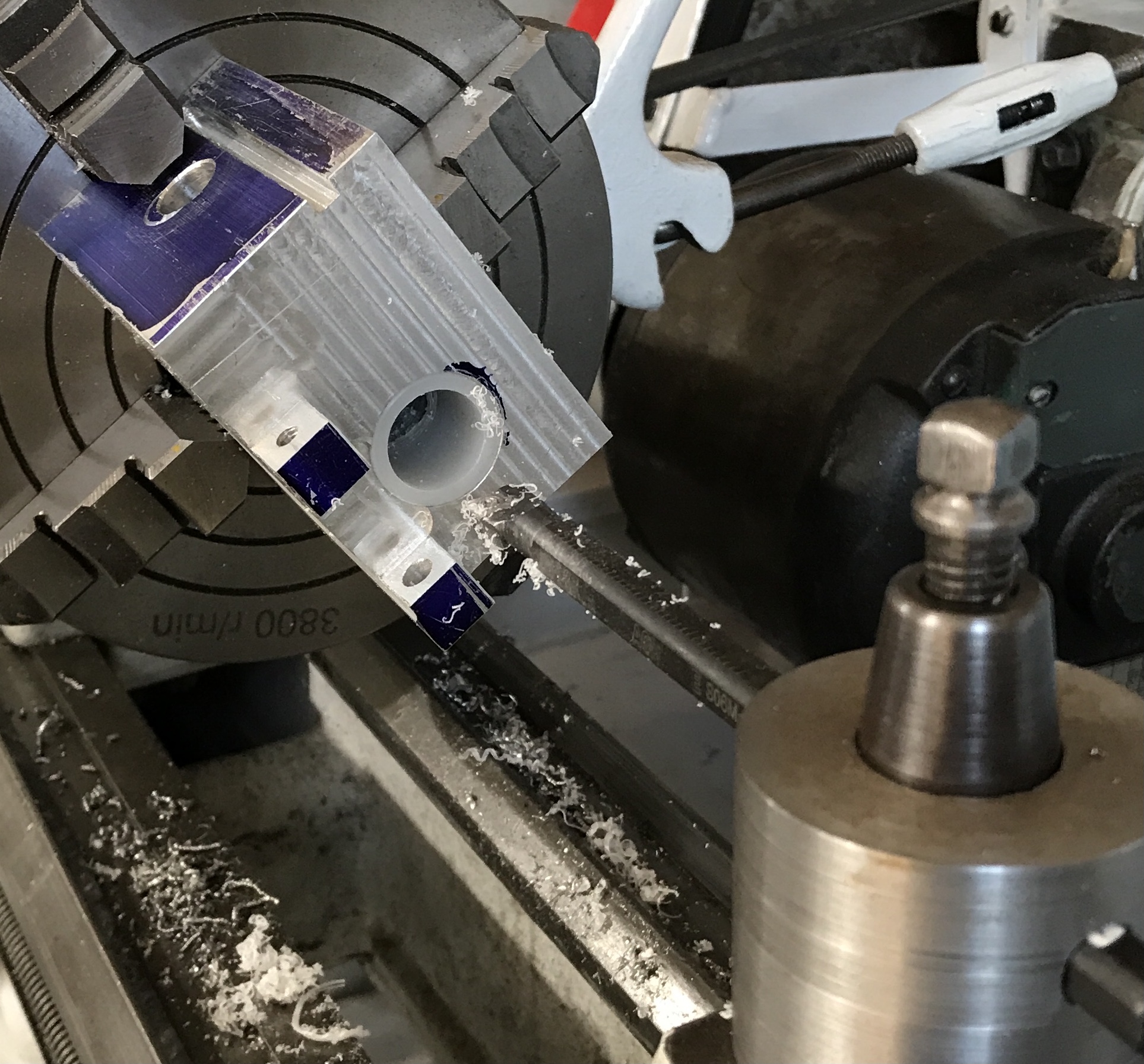
Tackled the body drilling and initial boring this morning in the unusually warm for February, 40° garage. The body was set up in the four jaw chuck so the marked hole was aligned with the tailstock center. The hole was drilled up to 3/4". The back gear was used for the 3/4" drill. The boring bar was installed on the toolpost and the first 1" of the hole was bored to 1". Again the back gear was used. (It is not very secure and pops out of gear if not careful!) Autofeed was also used. The part was then turned around and the other end of the drilled hole was bored to 1" for a depth of 1". The third picture below shows the completed boring for the bearing next to the tea needed for warming the borer. The center 1" that is 3/4" diameter also needs to be bored out to slightly larger than 3/4", so it does not interfere with the movement of the 3/4" ram.
The 1.5" of 3/4" central hole was bored open by 1/32" to allow free passage of the ram. The wider bored ends were measured. Both were 0.83" deep. One was 1.001" in diameter and the other was 0.984" in diameter. A 0.83" length of the purchased nylon rod was cut off and hammered into the larger bore with the plastic hammer head. A length of nylon was cut off and reduced to 0.986" diameter. It was cut off at 0.83". It was drilled with a #19 drill just to allow for air release. It was hammered into the smaller bore. The body with nylon bearings was centered in the four jaw chuck on the South Bend lathe using a tailstock center. An attempt was made to drill out the two bearings with a 5/32" drill. It got stuck and pulled the first bearing out of the bore! The bearings will be glued in when the new two part epoxy arrives.
While waiting on the epoxy attention was returned to the yoke. The yoke was held on a block of wood on the mill table as seen below. Each side was cut in small increments. One side needed about 1/16" removed and this was done by aligning the end mill with the scribed line and cutting down in 0.025" passes. The other side required less material removed and the end mill was lowered in 0.050" increments. The 1/4" four flute end mill was used at 700 rpm. The pivot is a nice fit in this slot.
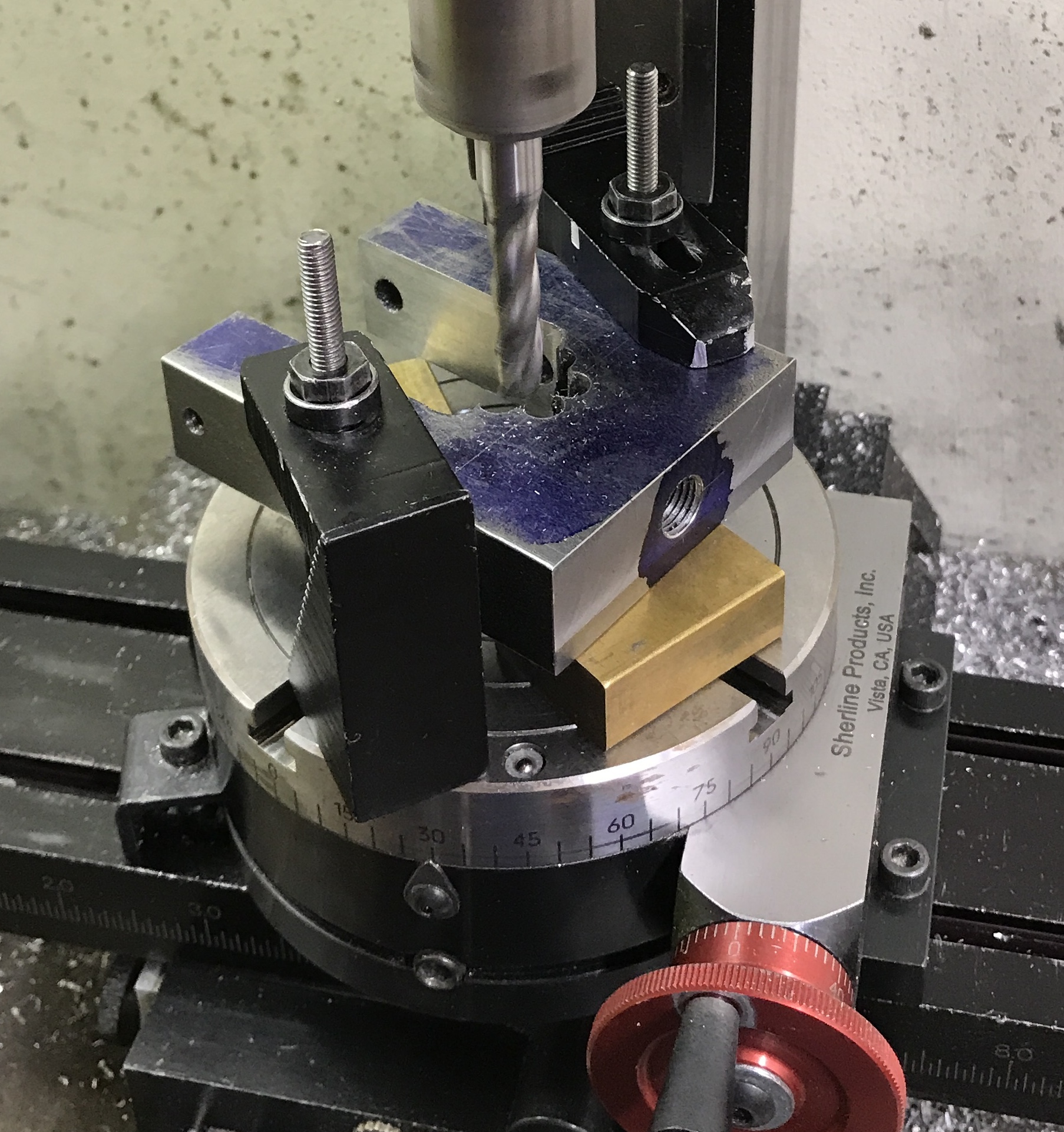
Performing the same cutting on the rounded end of the slot was tackled next. The yoke was set up on spacers on the rotary table. The table was centered under the spindle. An attempt was made to align the imaginary center of the yoke's semi-circle. The table was moved in the y-direction in 0.050" steps. The end mill was lowered 0.050" and the table was rotated through 180°. After lowering the end mill 15 times the table was again moved another 0.050". After a few passes it became clear that the yoke was not centered under the spindle. This will need to be fixed before cutting any further.
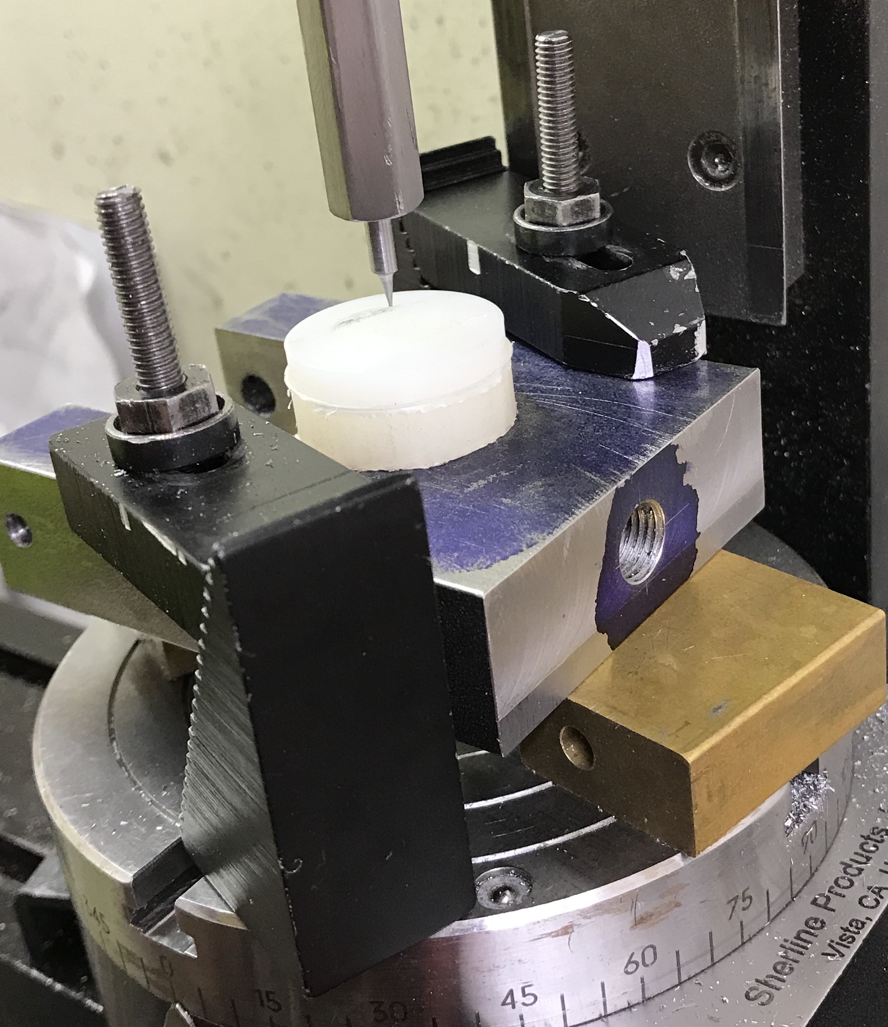
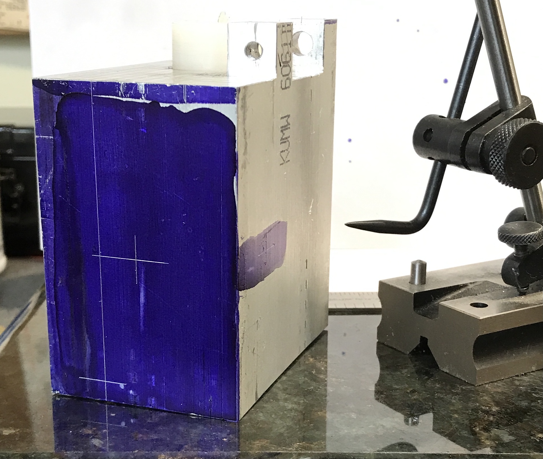
A path forward was devised last night. A plastic cutoff that is 1" in diameter has a small hole in the center. A square of carpet tape was affixed to one side and cut to the diameter of the plastic. This was carefully attached to the yoke aligning the plastic cylinder with the scribed semi-circle on the yoke. After re-centering the rotary table the center of the plastic was aligned with the stub. It was clamped down tight with two strap clamps. The picture shows the process though the aligning hole in the plastic is not visible.
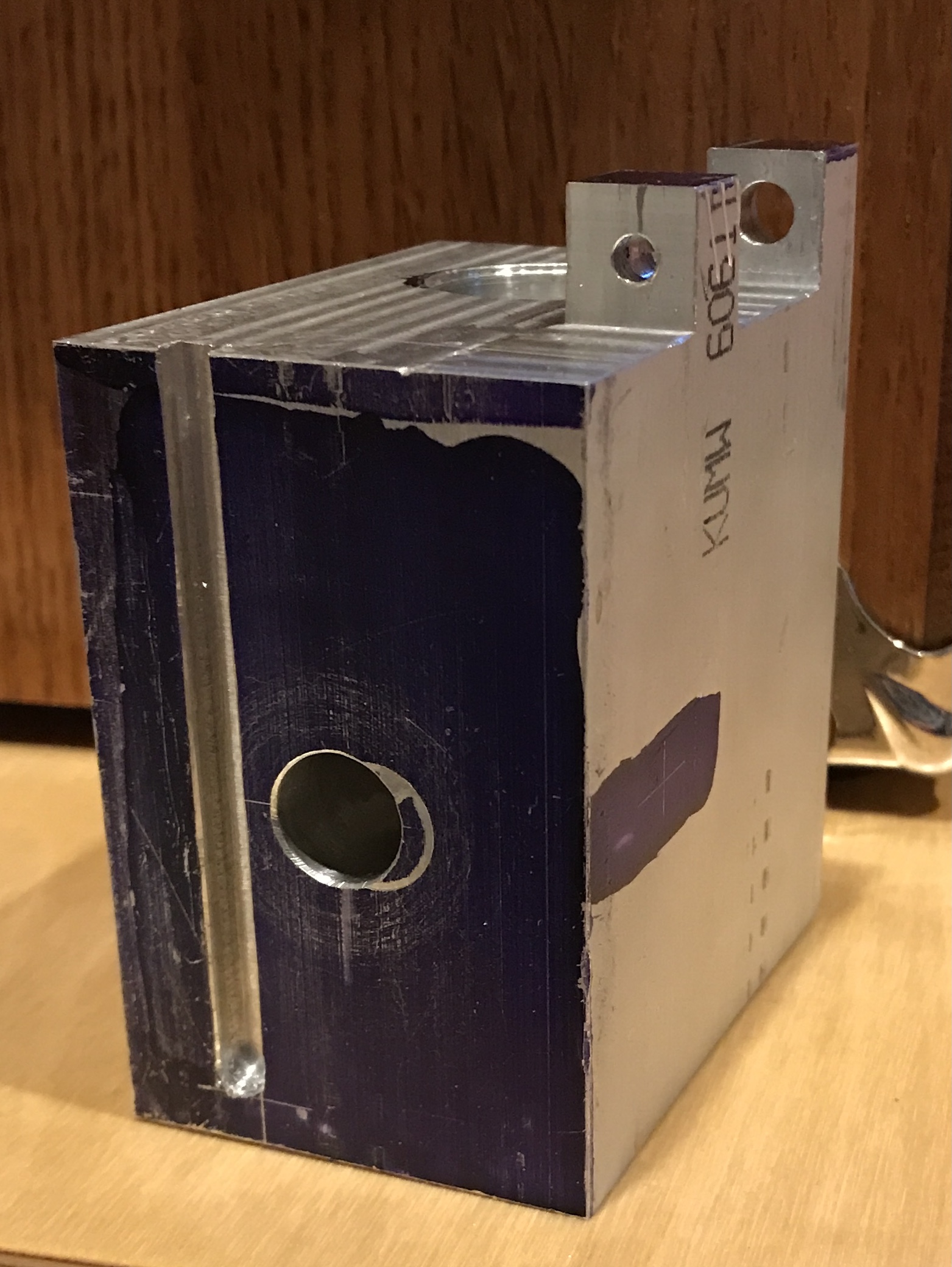
The remaining material was removed in cuts of 0.050" X 0.050". It was necessary to guess how deep to go as the scribed semi-circle was no longer visible. The last few cuts were 0.010" deep and used the full length of the end mill to remove the material in one pass. I may have gone a few thousandths too far. The cut looks really good though. The surface finish is excellent. A minimal amount of deburring and sanding and the Yoke de Triomphe was finished.
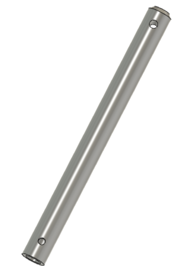
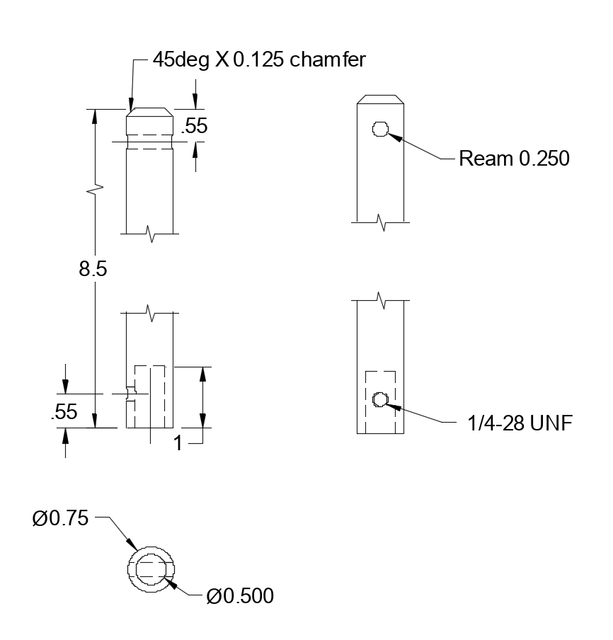
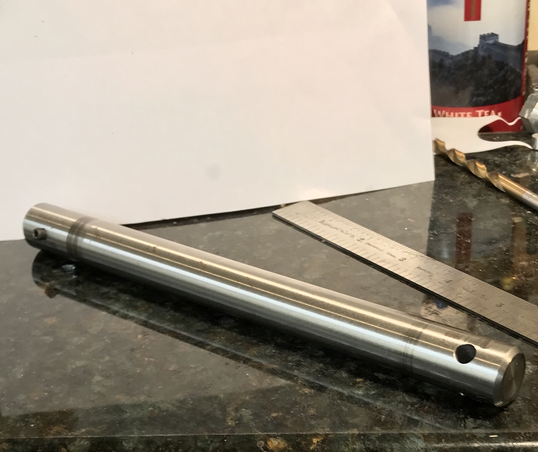
The ram was next on the list. It was fairly straightforward, though a little large. The bar of 3/4" ground and polished rod was cut to 8.5". It was held in the small lathe with a three jaw chuck and the steady rest. The end was checked for concentricity. The end was faced and a large 45° chamfer was put on the end with a file. The stock was flipped end for end in the lathe and faced. A 1" deep hole was drilled with successively larger drills up to 31/64". The hole was reamed to 1/2". The last drilling and the reaming had to be moved to the South Bend lathe in the frigid garage.
The part was held on a vee block with two strap clamps. The end with 1/2" hole was located as was the center of the stock 0.500" from the end. A hole was drilled and tapped 10-32. It was cleaned up and a set screw was installed. (The plans called for a 1/4-28 set screw, but I don't have any.) The opposite end was drilled and reamed 1/4" through, 0.500" from the end. This completed the ram, shown in the photo below.
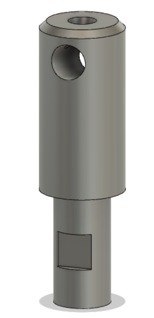
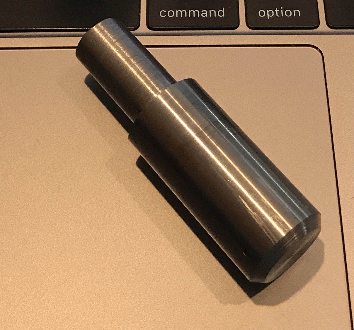
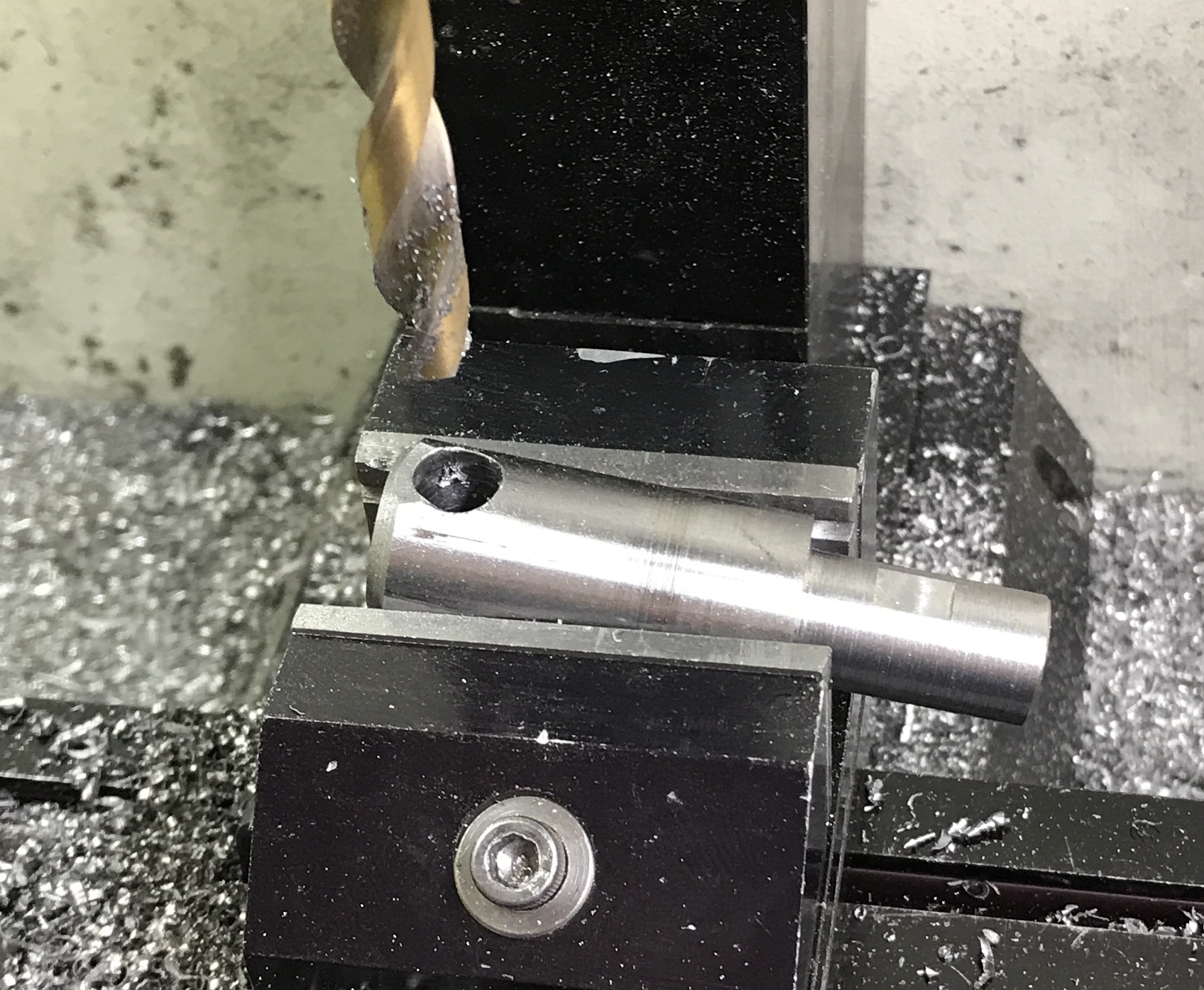
Well that was ridiculous! An attempt was made to construct the tool holder. A 2.5" length of the ground and polished steel was cut off with a hacksaw. This was held in the chuck and faced. A portentous chatter was experienced even when removing only 0.005". I was barely able to fit the steady rest between the carriage and the closest approach of the cross slide in order to make the 0.93" long reduction in diameter. Even with the steady there was tremendous chatter even during a 0.005" cut. The cutting was switched from the tangential tool to the HSS insert tool. This was no better. This part will have to be made using the South Bend lathe in the garage, when the weather warms next week. In the meantime a photo documenting progress to date.
Moved the work out to the South Bend in the garage at 40°. It was quick work. The end was refaced and the diameter was reduced to just a bit more than 0.500" for 0.93". It was a tight fit that was corrected by sanding. This resulted in a sliding fit with a vacuum releasing 'pop' when the tool holder is pulled from the ram. The chamfer on the other end was increased to the plan size.
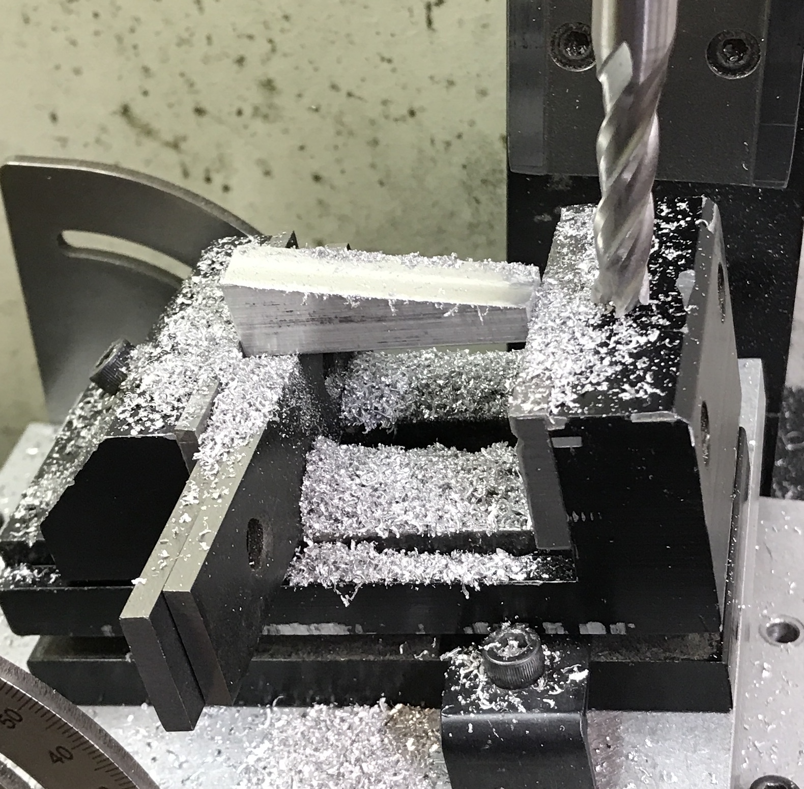
In order to drill the cutting tool hole at 10° an angled support needed to be made. The angle plate was set at 10° and measured to make sure it was correct. The vise was attached and a bar of aluminum scrap was held in the vise after squaring the ends. It was milled in 0.010" increments as there was a lot of chatter with deeper cuts. The vise was returned to the mill table and the tool holder was mounted on the new angle plate and securely held. A flat was milled onto the end of the tool holder. A mark was made at 0.218" for drilling. A center drill was used first followed by four drills to get to 5/16". A lot of cutting fluid was utilized. The photos show the angle plate and the drilled hole.
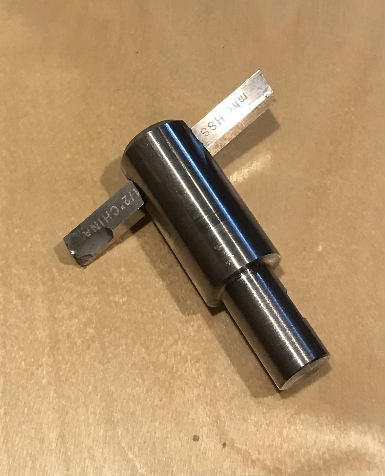
The recommended way to ensure the crosshole for the set screw is perpendicular to the angled tool hole is to drive a 1/4" square tool bit through the hole and use this to suspend the tool holder for drilling. Easier said than done. The hole was first marked and then four corners were filed in the 5/16" hole. This was fairly simple. The tool bit was then hammered through on the tail of the vise in the garage. It was not easy to drive the bit through and ensure it was aligned with the hole. In any event it was eventually driven through as shown in the photo below. The damage to the bit can be seen.
Per the article the tool holder was suspended on 7/8" parallels in the drill press vise and set on the small drill press. The center was aligned under the spindle and the vise clamped to the table. The holder was center drilled and then drilled with a #25 drill prior to tapping 10-24 to match the largest set screw in my stock. The tool was knocked out with a hammer. Not the best way to slide a tool in and out of the holder. I will need to do some filing to make tool installation easier.
I will work on the bearings this afternoon. In the meantime the 0.5" support hole and the keyway need to be added to the body. Both are on the narrow face opposite the ram hole. The hole is centered on the 2" dimension and 1.5" from the bottom. The slot is 0.38" from the center of the hole. The 3/16" slot extends from the top to 0.22" from the bottom. The slot is 0.094" deep and the hole is 1.125" deep. The hole needs to be finished flat-bottomed. These features were marked as well as the hole for the set screw 1.5" up and 3/4" in from the hole and slot side.
The body was held against the angle plate with a bar clamp. The spindle was aligned with the mark and the hole was center drilled and drilled up to 7/16". It was moved to the vise on the drill press. The hole was then drilled up to 1/2" to a depth of 1.125" (based on the tip of the drill). Again in the drill press a 1/2" end mill was installed in the chuck. The bottom of the hole was milled flat. The hole measured 1.130" deep. This took all of the morning as many different attempts for drilling and milling were tried and discarded.
The body was clamped again to the angle plate in preparation for slot milling. Using the spud the scribed line for the slot was aligned with the spindle. The table was moved 0.094" and clamped on the y-axis. A 3/16" end mill was used to cut the slot in increments of 0.010". After milling 0.094" deep the key from the lathe was inserted. The fit was too tight so the slot was widened about 0.003". The height of the key remaining above the body was measured at 0.130". The key is not square. The slot was made 0.030" deeper for the key to fit about halfway. The photo shows the deburred slot adjacent to the 0.5" hole.
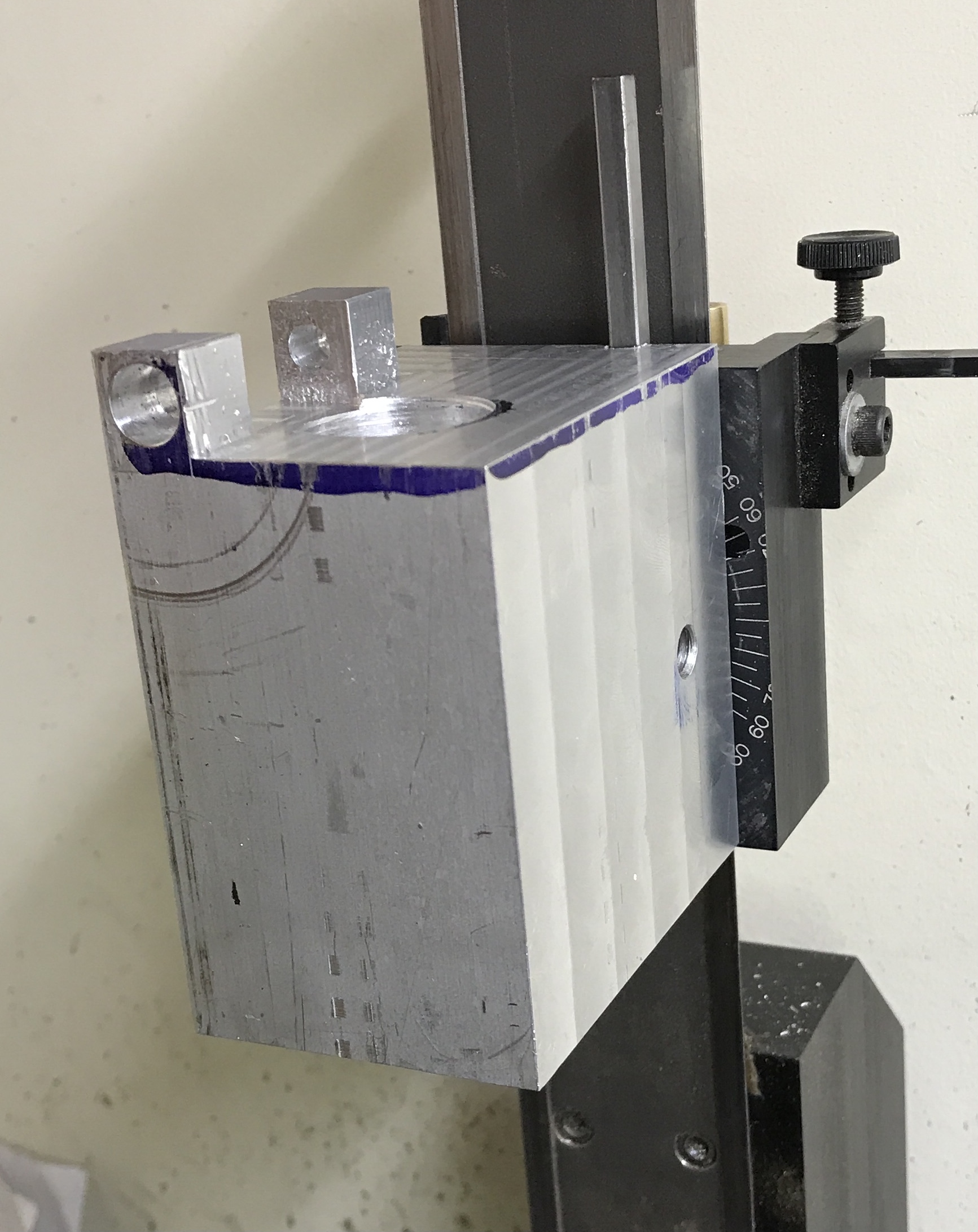
Drilling the set screw hole was straightforward, but … The spindle was aligned, the hole was started and drilled with an "F" drill. The hole was tapped 5/16-18 as that is the match for the Sherline set screw. The fit was tried out after removing the headstock. It was very loose and no amount of fiddling made it any tighter. I realized at this point that the hole needs to be 23/32" from the back of the body not 3/4". So the opposite side was marked out and the same procedure as above followed. Still did not fit, but this time fiddling around gave a tight fit. The key is that the key cannot go all the way into the slot(?). The photo shows the proper setup to get a tight fit.
The nylon bearing that had been pulled out of the body during drilling was drilled up to 31/64 on the Sherline lathe. A little oil helped control the tendency of the drill to pull the bearing out of the chuck. A plug was made for the unused set screw hole. A 3/8" aluminum rod was reduced to 5/16" for 1/2". After threading 5/16-18 it was screwed into the hole with a few drops of Loctite. The stub was sanded off after the glue dried.
It was 42° in the garage this morening so it was time to finish drilling and do some boring. The block was held in the four-jaw chuck and the previously drilled hole was used to center the bearings. This hole was drilled to 1/2" from its 31/64" just to make sure all was in order. The undrilled bearing on the back side could not be drilled without pushing it out of the body. The part was turned around in the chuck after marking the center of the opposite bearing. It was close enough to center for the boring operation to take care of any misalignment. It was center drilled and drilled up to 1/2". The drilling went very well with no incidents of bearing pullout!
The boring bar was installed so that it would pass all the way through the 3" body and bore both bearings simultaneously. The body was returned to the first, centered position in the chuck. Boring was done in 0.015" increments. These went very well. It was necessary to stop about 2/3 of the way through and remove the stringy chips filling up the space between the bearings. The bore was measured as it got close to size. Once it was within a few thousandths, the ram was used to test the fit. After getting a tight fit an additional 0.001" was removed and this gave a perfect sliding fit.
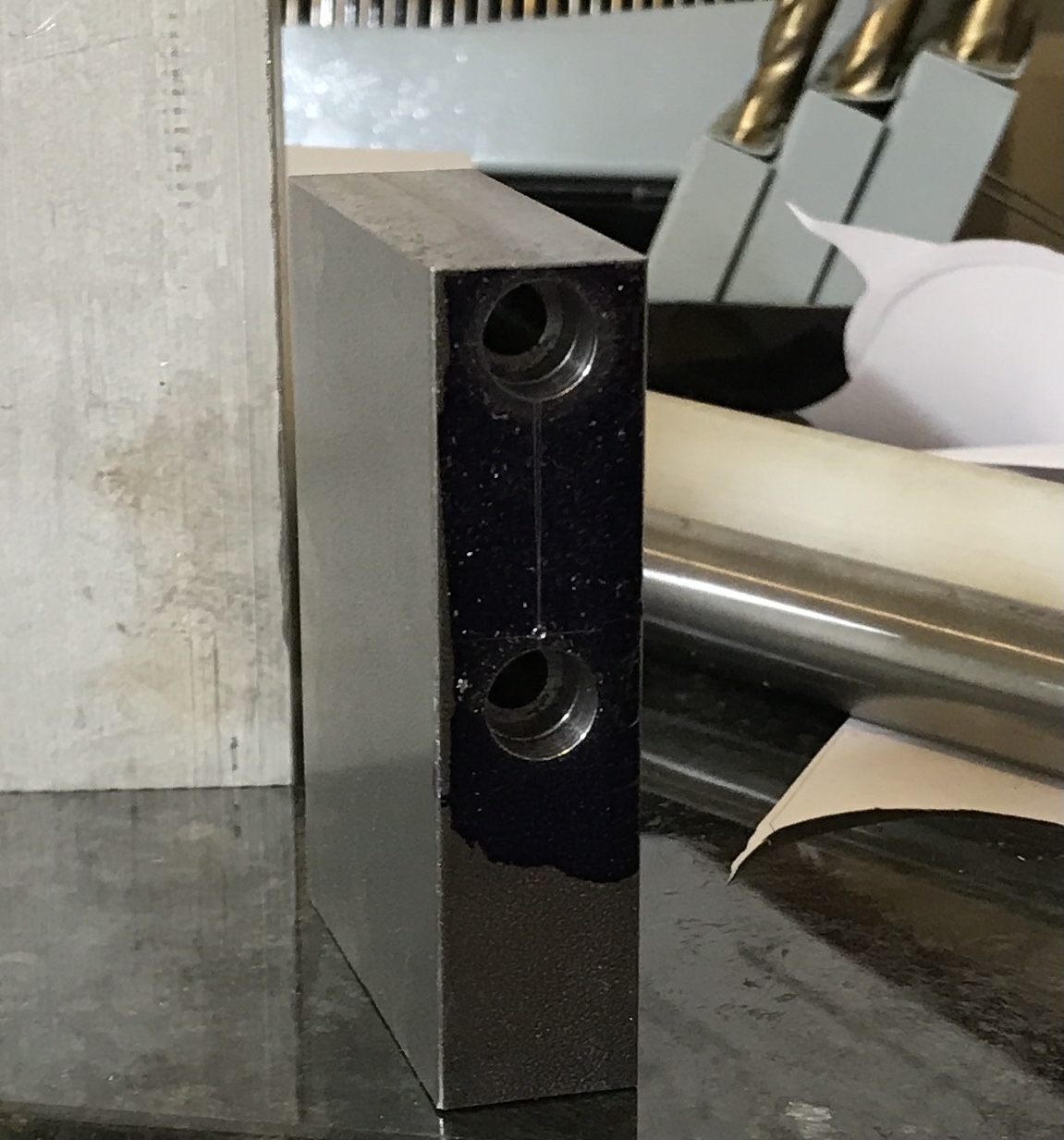
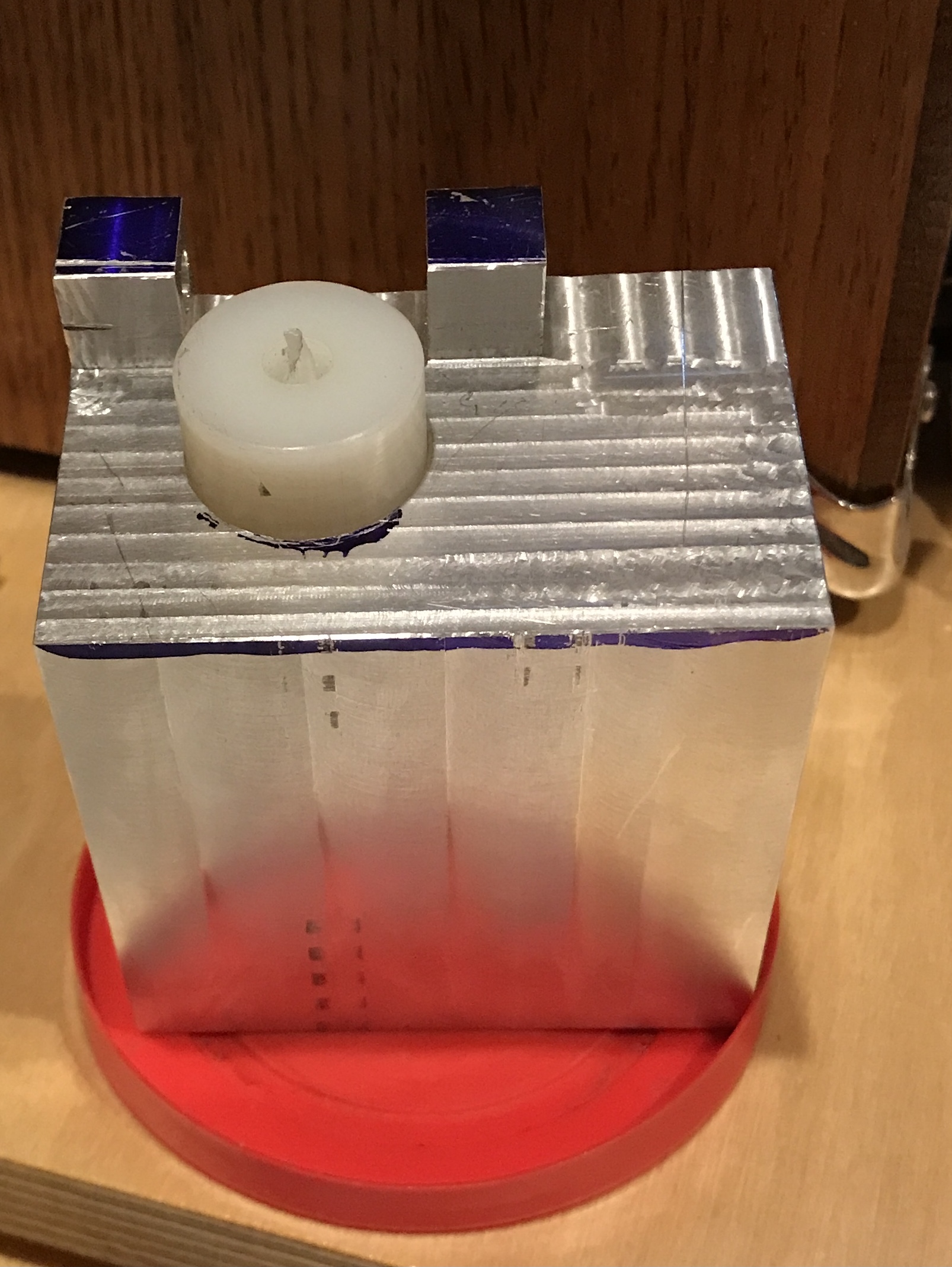
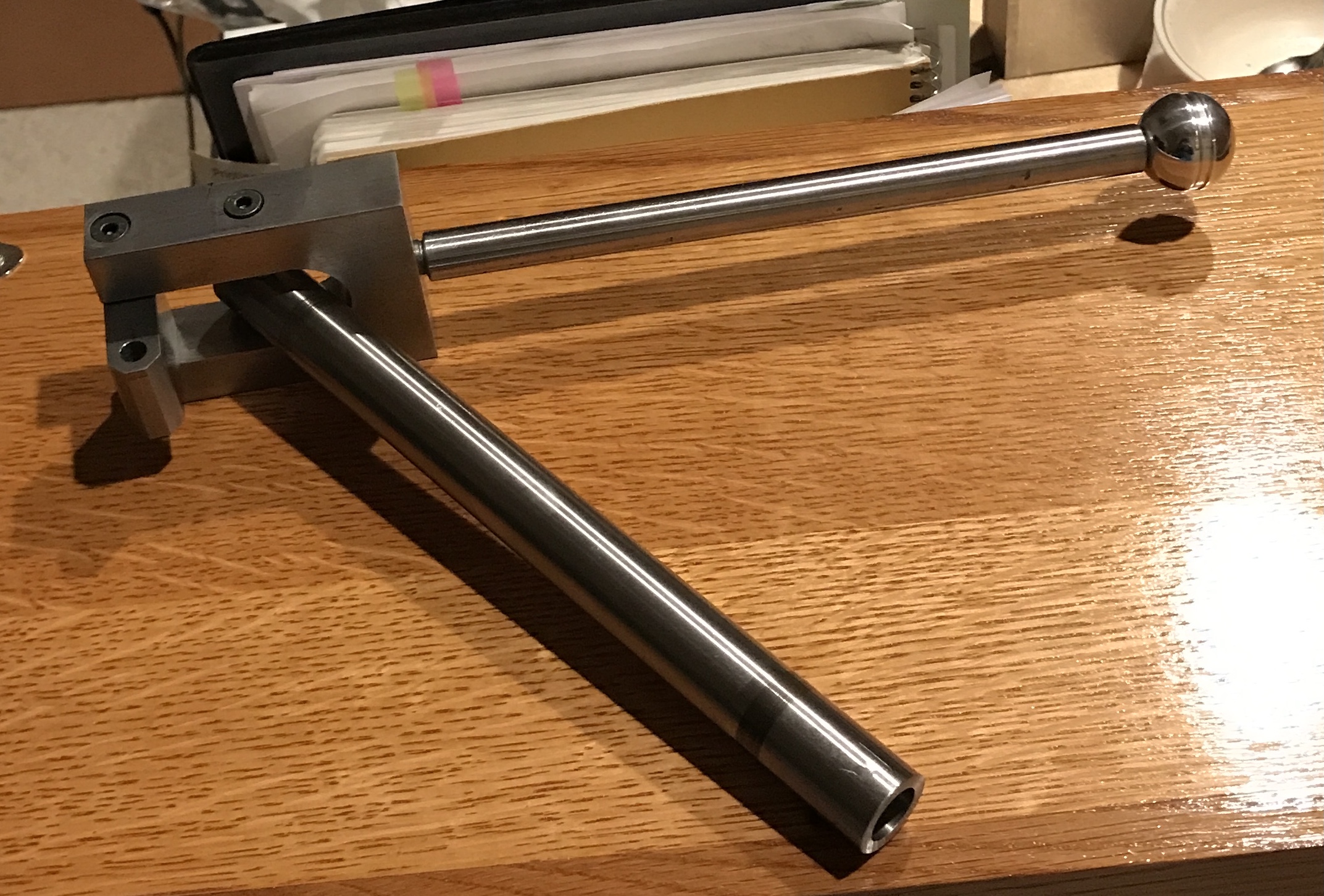
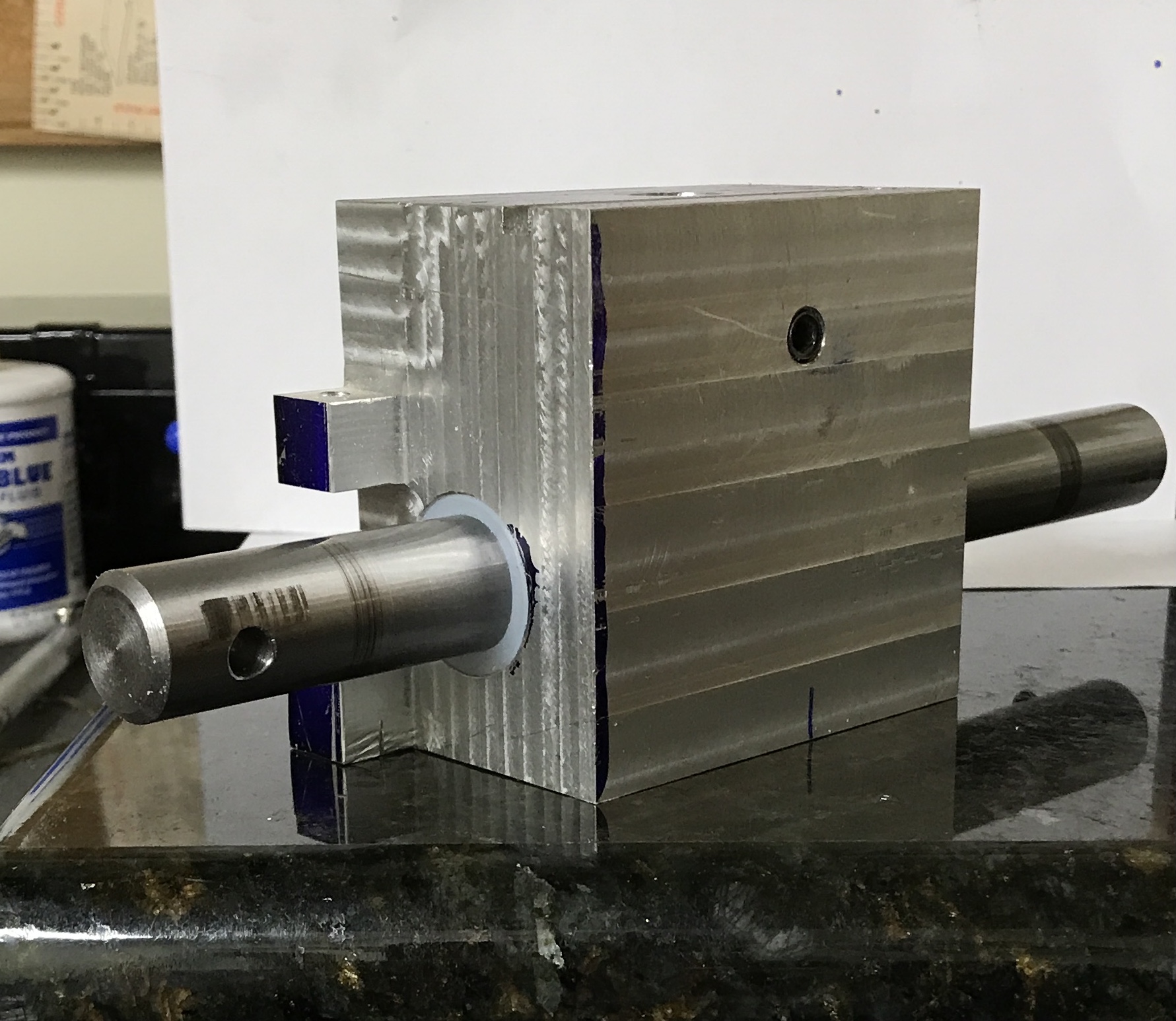
The body was removed from the chuck. The back bearing had a huge burr that ran all the way around the hole. This was removed and the front bearing was also deburred. The body, pivot, yoke, handle, and ram were assembled for testing. The movement is smooth. The assembled slotting attachment is shown below.
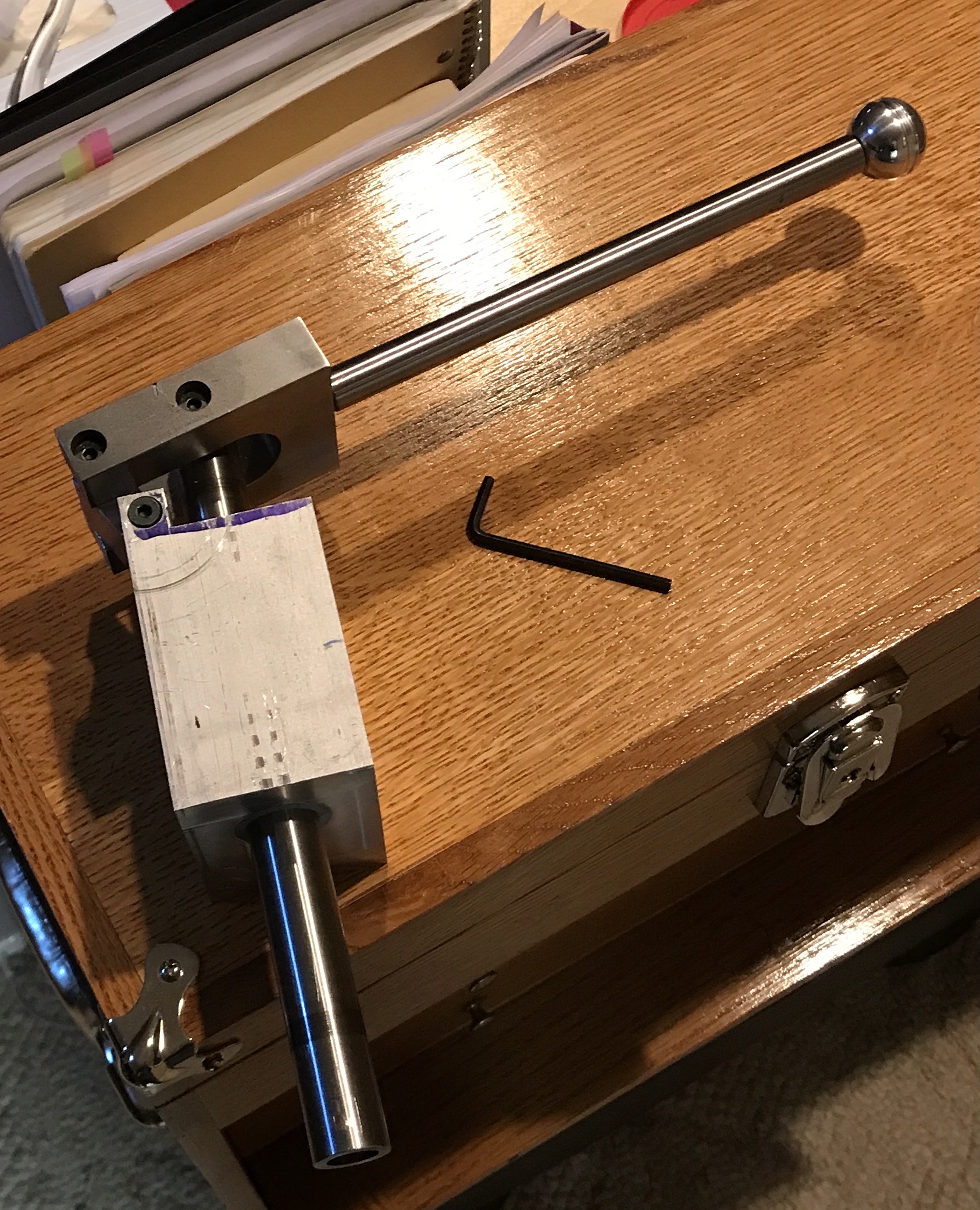
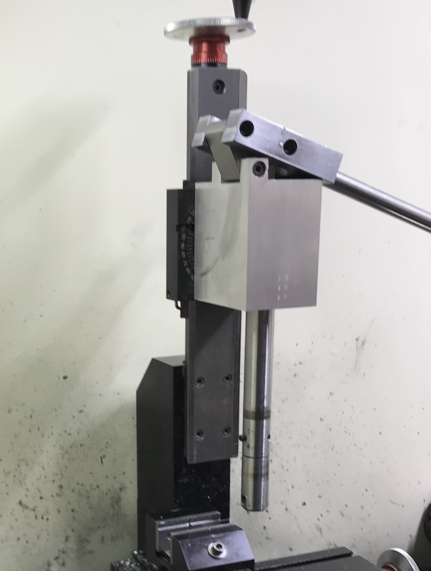
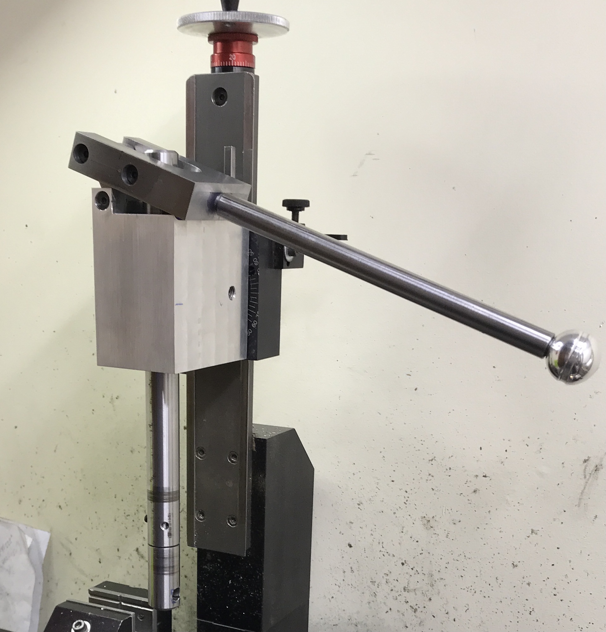
Below are three shots of the lightly sanded, assembled, and installed slotting attachment. I can't wait to make a tool and try it out.
Per the business card project a tool was ground for the internal gear. It was forced into the ram and the slotter was installed on the Sherline mill. There is some play in the ram movement and that gave a less than ideal cut. The attachment was removed and taken apart. The bottom bearing (back bearing when bored) is oversized at 0.760". I decided the simplest repair was to glue a piece of nylon into the bearing and rebore.
The body of the slotting attachment was returned to the South Bend lathe. Luckily the chuck was still set up from the previous boring job. The back bearing (or bottom) was bored out an additional 0.025" at which point the space between the two bearings was just being scraped by the boring bar. The bearing opening measured 0.784". A scrap of the nylon was faced and reduced to 0.782" in the Sherline. The part was drilled up to 31/64 fairly easily only producing some hot drills. It was parted off at 3/4". After deburring two-part epoxy was used to glue the insert in place.
This morning the budgied bearing was bored to fit the ram. The top bearing, as done previously, was dialed in with the dial indicator held in the tailstock chuck. The bottom bearing was bored until the ram just fit. After removing the body from the chuck and reassembling the slotter, there was no observable play in the ram.